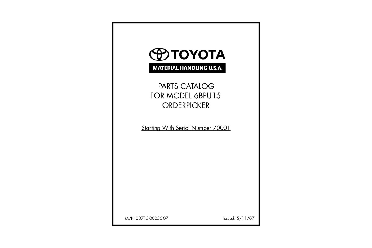
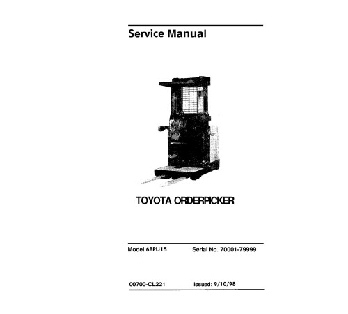


Illustrated factory set of Service Manuals for Toyota Order Pickers Models 6BPU15 (SN:70001-79999).
This manuals will assist you in assembling, disassembling, repairing, troubleshooting, and finding spare parts for your order picker.
You can use a Windows, Mac, or Android device to view this manuals. You only need to have a PDF reader installed.
Covered Models:
6BPU15 (SN:70001-79999)
The manual comprises 3 documents, including the Repair Manual, Wiring Diagram, and Parts Catalog
1. Repair Manual (RM-CL221)
Format: PDF, 456 pages
Language: English
Table of Contents:
How to Use This Manual
Map of the Manual
Manual Design
Table of Contents
List of Figures
Start Page
Safety
Definitions
General Safety
Battery Safety
Static Safety
Jacking Safety
Tie-down for Transport
Towing
Welding Safety
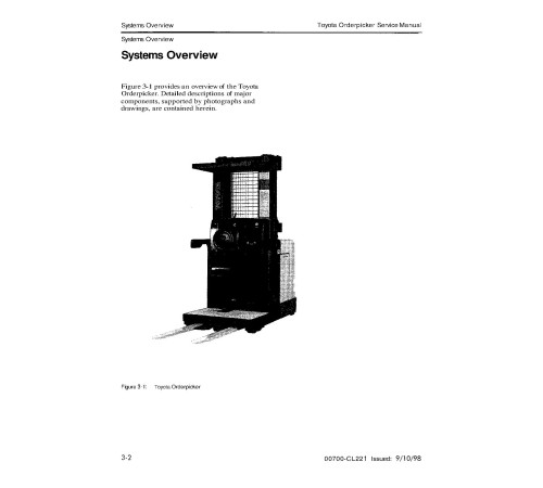
Systems Overview
Systems Overview
Type
Power
Capacity
Mast
Controls
Indicators
Electronics
Electric Steering System
Specifications
Description
Chassis
Operator's Console
Operator Compartment Options
Steering and Controls
Steer Controller Guidance System
Drive and Brake
Drive Unit
Brake
Mast
Mast Assembly
Hydraulic Components
Lift / Lower System
Electrical Components and Systems
General
Miscellaneous Circuits
Fuses
Sidegate Switches (S60, S61)
Tie-Points
Cables
Over-the-Mast Cables
Planned Maintenance
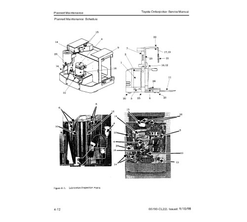
Planned Maintenance
General Maintenance Instructions
Planned Maintenance
Introduction
Maintenance Manual
Battery Maintenance
Battery Safety
Battery Inspection and Care
Battery Cleaning Procedure
Charging Process
Troubleshooting
How to Use This Chapter
Electrical Troubleshooting Guidelines
Electrical Connector Locator Chart
Shorts to Frame Test
Electric Motor Tests
Motor Types
Open Circuit Motor Test
Grounded Motor Test
Short Circuited Armature or Field Winding
Hydraulic Troubleshooting Guidelines
Hydraulic Leakage
List of Troubleshooting Charts
Electrical Codes and Tests
General
Modes of Operation
Overview
Passwords
Disable the Brush Wear Warning
Entering the Secondary Password
Start the Hour Meter
Entering the Secondary Password
Self-diagnosis Mode
Maneuvering within Self-diagnosis Mode
Analyzer (AnL) Mode
Entering the Secondary Password
Entering Analyzer Mode
Maneuvering within Analyzer Mode
Tuning (Tuning) Mode
Entering the Secondary Password
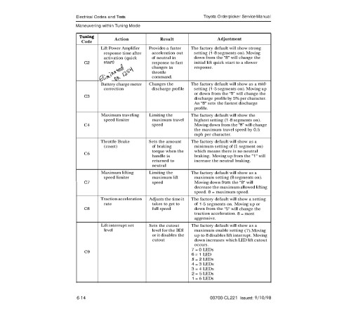
Maneuvering within Tuning Mode
Exiting Tuning Mode
Calibrate (Calibrte) Mode
Entering the Secondary Password
Entering Calibrate Mode
Maneuvering within Calibrate Mode
Configure (Configur) Mode
Entering the Secondary Password
Code Summary Tables
Analog Inputs
Category 1 Class 2:
Tests
Steer Controller Guidance Systems
Codes and Tests
Steer Controller Guidance System
Analog Input Tests: (Category 1, Class2: 12)
12-20: Steer Controller Power Supply Voltage
Steer Controller Guidance System
Digital Input Tests
Component Procedures
Component Locator Photos
General Maintenance Instructions
Maintenance Practices
Adjustment and Repair
Power Section
Theory of Operation
Electrical Functions
Operating Description Overview
Lift / Lower System
Overview
Unique System Features
Lift
Lower
Braking System
Proportional Plugging
Appendix
Lubrication Equivalency Chart
Torque Chart - Standard (Ferrous)
Torque Chart - Standard (Brass)
Torque Chart - Metric
Decimal Equivalent Chart
Standard / Metric Conversions
Electrical Schematic
Hydraulic Schematic
Index
2. Wiring Diagram (EL-CL221)
Format: PDF, 8 pages
Language: English
3. Parts Catalog (PM-00715-00050-07)
Format: PDF, 252 pages
Language: English
Table of Contents:
General Information
To Our Customer
How To Use Parts Catalog if Part Number Is Not Known
How To Use Parts Catalog if Part Number Is Known
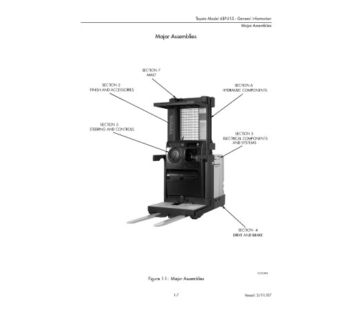
Major Assemblies
Recommended Spare Parts List
Hardware Parts List
Finish and Accessories
Major Assemblies
Finish Details
Battery Gate Installation
Sidegate Installation
Platform and Pallet Clamp Assembly
Pedal Assembly, Pallet Clamp
Platform Extension Assembly (47 in. to 55 in.)
Platform Extension Assembly (59 in. to 63 in.)
Guide Roller Assembly Weldment (71.75 in. Roller Width)
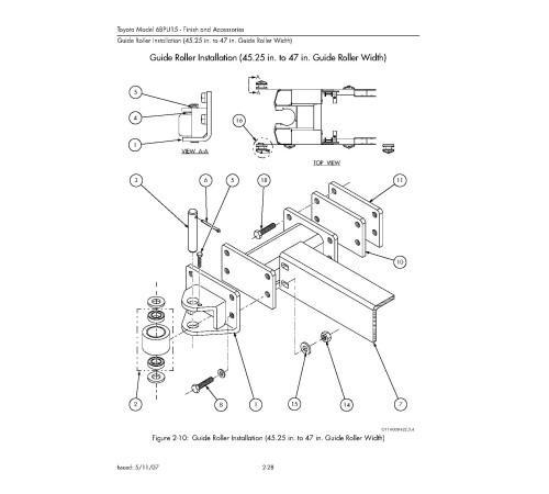
Guide Roller Installation (45.25 in. to 47 in. Guide Roller Width)
Wheel Assembly, Switched
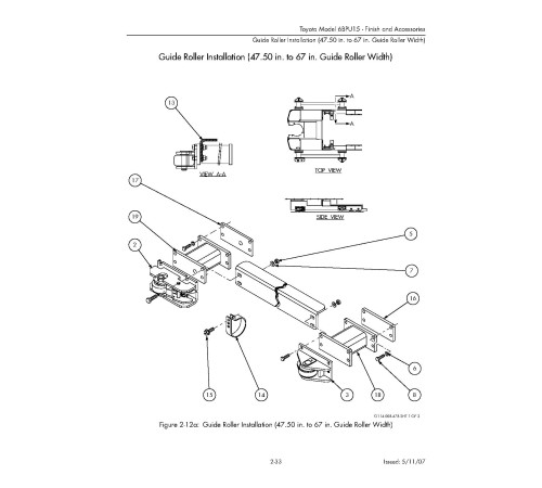
Guide Roller Installation (47.50 in. to 67 in. Guide Roller Width)
Roller Switch Assembly (2.25 in. x 3.12 in. Wheel)
Guide Roller Installation (52 in. to 67 in. Width, With 44 in. BLO)
Guide Roller Installation (Guide Roller Width 61.25 in. to 66.75 in. With 56 in. BLO)
Fire Extinguisher Installation
Mast Guards
Tether, Mechanical Installation
Battery Accessories
Steering and Controls
Steering and Control Components
Steering Wheel Assembly
Steer Motor and Gearbox Assembly
Drive and Brake
Drive and Brake Components
Motor and Drive Unit Assembly
Lower Drive Unit Assembly
Deadman Brake Components
Brake Installation
Brake Assembly
Deadman Brake Assembly
Wheel Assembly, Standard, Rounded Black Tire
Electrical Components and Systems
Electrical System
Carriage Electrical Assembly
Contactor Assembly
Contactor
Steer Control Assembly, Toyota Tracker
Display, Controller
Wire Guide Installation
Wire Guidance Sensor, Tractor End
Wire Guidance Sensor, Load End
Warning Light Installation
Warning Light Assembly
Battery Connector Assembly
Operator Compartment Lights and Fan, Standard
Light and Fan Assembly, Fluorescent
Light and Fan Assembly, Incandescent
Bin Lights Installation
Bin Light Assembly
Auxiliary Power Hookup
Lift Limit Cutout Switch Installation
Travel Limit Switch Installation
Lower Limit Switch
Tractor Heaters, Cold Storage
Motion Alarm Installation
Motor Drive, 24 Volt
Motor, Lift, 24 Volt
Control Handle Assembly
Hydraulic Components
Hydraulic Installation
Reservoir Assembly
Lift/Lower Manifold Assembly, Three Stage
Valve, Lift/Lower, Three Stage
Lift/Lower Manifold Assembly, Two Stage
Valve, Lift/Lower, Two Stage
Lift Pump and Motor Assembly
Lift Ram, Main Lift, 1.75 inch Diameter
Lift Ram, Free Lift, 2.5 inch Diameter
Mast
Two Stage Mast Assembly
Three Stage Mast Assembly
Two and Three Stage Mast Cables, Hoses and Pulleys
Fork Assembly, Standard
End Cap Pulley Assembly
Pulley Assembly
Bumper Assembly
Load Wheel Assembly
Included
Wiring Diagram
1Parts Catalog
1Reviews: 0
There are no reviews for this product.
Questions: 0
No questions about this product.
Похожие товары

