

$49.99
Fault Codes List
3Service Manual
5Technical Manual
2Operate and Maintenance manual
1Wiring Diagram
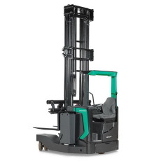
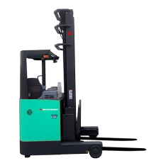
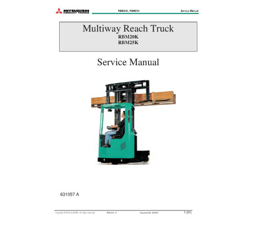
2Illustrated factory set of Service Manuals for Mitsubishi Reach Trucks Models RBM20K and RBM25K.
This manuals will assist you in determining a malfunction using a fault code, diagnosing, analyses, testing, repair, repairing, operating, maintaining, and troubleshooting for your reach truck.
You can use a Windows, Mac, or Android device to view this manuals. You only need to have a PDF reader installed.
Covered Models:
RBM20K
RBM25K
The manual comprises 15 documents, including three Fault Codes Lists, five Service Manuals, two Technical Manuals, the Operate and Maintenance manual, two Wiring Diagrams, and two Hydraulic Circuit Diagrams
1. Fault Codes List (Traction_and_pump_controller)
Format: PDF, 1 page
Language: English
2. Fault Codes List (Steering_inverter_errors)
Format: PDF, 1 page
Language: English
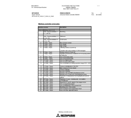
3. Fault Codes List (Multiway_controller_errors)
Format: PDF, 1 page
Language: English
4. Service Manual (SM-631057A_16)
Format: PDF, 95 pages
Language: English
Table of Contents:
FOREWORD
HOW TO READ THIS MANUAL
Safety-related signs
Symbols and abbreviations
Units
SAFETY INSTRUCTIONS
Service area safety
Personal safety
Work safety
GENERAL INFORMATION
Truck model covered by this manual
Identification plates on the truck
FORKS
Fork inspection
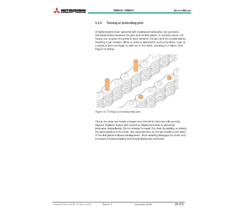
Mast chains
ELECTRICAL OPERATION
How to use the schematic diagram
Power source
Safety circuit (emergency stop button)
Key switch
Traction
BATTERY MAINTENANCE
Safety regulations concerning the handling of lead-acid batteries
Battery maintenance
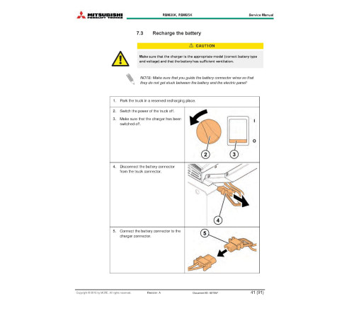
Recharge the battery
Measure the specific gravity of the battery
Replace the battery
ELECTRIC SYSTEM MAINTENANCE
Electric system
Controllers
Controller installation
Connections
Power stages
Control stages
PARAMETER LISTS
General instruction
Setup using the hand-held terminal
FAULT AND STATE REPORTS
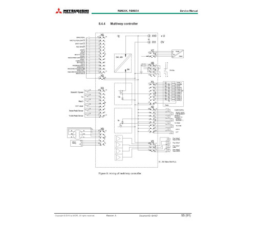
List of muitiway controller
Traction and pump controller
Steering controllers
TECHNICAL DATA
RBM20K, RBM25K
Mast heights
ANNEX
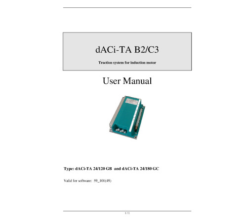
5. Service Manual: dACi-TA B2/C3 Traction system for induction motor (dACi2-EN)
Format: PDF, 27 pages
Language: English
6. Service Manual: CANION (CANION_0300)
Format: PDF, 38 pages
Language: English
Table of Contents:
Introduction
About CANION Documentation
Technical Description
Principles of Operation
Applications
Order Picker
Order Picker
Interfacing to CANION
Interfacing Input Devices
Interfacing Input Devices
Interfacing Output Devices
Can Bus Communications
Installation and Wiring
CANION Installation
CANION Installation
Specifications
Electrical Power Inputs & Outputs
7. Service Manual: Advanced Power Steering (APS-Advanced_Power_Steering)
Format: PDF, 55 pages
Language: English
Table of Contents:
Table of Contents
Introduction
About APS Documentation
About the Advanced Power Steering Unit
APS Installation
Installing APS in Vehicle
Installing Steering Feedback Sensors
Installing Steering Input Sensors
Wiring the APS
Startup and Commissioning
Initial Startup
Maintenance
Maintenance Procedures
APS Replacement Procedures
Troubleshooting
Introduction
The Troubleshooting Guide
8. Service Manual: AC Superdrive (AC-SuperDrive)
Format: PDF, 53 pages
Language: English
Table of Contents:
Scope of this Manual
Related Documents
Intended Use of the AC SuperDrive
Product Identification
Technical Support
Product Warranty
Introduction
Tools and Equipment Required
Orientation
Clearances for Access and Air Circulation
Procedure
Introduction
Tools and Equipment Required
Motor and Battery Connections
General
Making Connections to Terminal Posts
Fuses
Inrush Current Limiting Resistance
Main Contactor
Key Start Input
Control and I/O Connections
General
ID0 and ID1 Inputs
Encoder Signals
Temperature Sensor
CAN Bus Signals
Crimping Contacts onto Signal Conductors
Installing Crimped Contacts in Connector Housing
General
Checks Prior to Initial Powerup
Verifying AC SuperDrive Readiness for Operation
Configuring the AC SuperDrive for the Application
Final Operational Checks in Vehicle
Introduction
Periodic Preventive Maintenance
AC SuperDrive Replacement Procedure
Drive Removal
Drive Installation
Scope of the Troubleshooting Guide
Using the Troubleshooting Guide
Organization of Troubleshooting Guide
About Errors and Warnings
Error Logging
Using the Troubleshooting Charts
Information for OEMs Preparing User Documentation
Symptom: Main Contactor doesn’t close after switching on Key Switch
Symptom: Fuse to Power Stage is blown
Symptom: AC SuperDrive Status Indicator is blinking or off
Symptom: Motor runs only at low speed and with a ticking sound
Error Code 1: Pulse Sensor Error
Error Code 2: Motor Temperature High
Warning Code 16: Power limited due to Motor Overtemp.
Error Code 4: Heatsink Temperature high
Warning Code 1: Power Limited due to Heatsink Overtemp.
Error Code 8: Overcurrent
Error Code 16: DC Bus High - hardware detected
Error Code 32: DC Bus High - software detected
Error Code 64: DC Bus Low
Error Code 128: No Charging DC Bus
Error Code 256: CAN - too many Errors
Error Code 512: CAN Watchdog Time-out
Error Code 1024: Missing “Okay to Start” from Truck Controller
Error Code 2048: Contradictory Commands from Truck Controller
Error Code 4096: Potentiometer Values Out of Range
Warning Code 2: Heatsink Temperature Sensor - Open Circuit
Warning Code 4: Heatsink Temperature Sensor - Short Circuit
Warning Code 8: Power limited - temp < -20 deg. C
Warning Code 32: Motor Temperature Sensor - Open Circuit
Warning Code 64: Motor Temperature Sensor - Short Circuit
Warning Code 128: Speed from Truck Controller Out of Range
Warning Code 256: Current Calibration Error
Warning Code 512: Reverted to Default Parameters
89R09003A_UM.pdf
Scope of this Manual
Related Documents
Intended Use of the AC SuperDrive
Product Identification
Technical Support
Product Warranty
Introduction
Tools and Equipment Required
Orientation
Clearances for Access and Air Circulation
Procedure
Introduction
Tools and Equipment Required
Motor and Battery Connections
Control and I/O Connections
General
Checks Prior to Initial Powerup
Verifying AC SuperDrive Readiness for Operation
Configuring the AC SuperDrive for the Application
Final Operational Checks in Vehicle
Introduction
Periodic Preventive Maintenance
AC SuperDrive Replacement Procedure
Obtaining Factory Repair
Scope of the Troubleshooting Guide
Using the Troubleshooting Guide
Information for OEMs Preparing User Documentation
Symptom: Main Contactor doesn’t close after switching on Key Switch
Symptom: Fuse to Power Stage is blown
Symptom: AC SuperDrive Status Indicator is blinking or off
Symptom: Motor runs only at low speed and with a ticking sound
Error Code 1: Pulse Sensor Error
Error Code 2: Motor Temperature High
Warning Code 16: Power limited due to Motor Overtemp.
Error Code 4: Heatsink Temperature high
Warning Code 1: Power Limited due to Heatsink Overtemp.
Error Code 8: Overcurrent
Error Code 16: DC Bus High - hardware detected
Error Code 32: DC Bus High - software detected
Error Code 64: DC Bus Low
Error Code 128: No Charging DC Bus
Error Code 256: CAN - too many Errors
Error Code 512: CAN Watchdog Time-out
Error Code 1024: Missing “Okay to Start” from Truck Controller
Error Code 2048: Contradictory Commands from Truck Controller
Error Code 4096: Potentiometer Values Out of Range
Warning Code 2: Heatsink Temperature Sensor - Open Circuit
Warning Code 4: Heatsink Temperature Sensor - Short Circuit
Warning Code 8: Power limited - temp < -20 deg. C
Warning Code 32: Motor Temperature Sensor - Open Circuit
Warning Code 64: Motor Temperature Sensor - Short Circuit
Warning Code 128: Speed from Truck Controller Out of Range
Warning Code 256: Current Calibration Error
Warning Code 512: Reverted to Default Parameters
um.pdf
9. Technical Manual: PARAMETER SETTINGS (PA-RBM20K_RBM25K)
Format: PDF, 7 pages
Language: English
10. Technical Manual: PARAMETER SETTINGS (PA-Adjustment_instructions_260406)
Format: PDF, 2 pages
Language: English
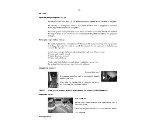
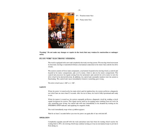
11. Operate and Maintenance manual (OMM-WHOMM0002)
Format: PDF, 27 pages
Language: English
Table of Contents:
FOREWORD
INSTRUCTIONS ON OPERA TING THE TRUCK
OCCUP A TIONALSAFETY
LOAD HANDLING
DRIVING
P ARKING
OTHER WORKINGINSTRUCTIONS
RECHARGING AND REPLACING THE BA TTERY
HAZARDOUS W ASTE AND DISPOSAL
ORDERINGSP ARE P ARTS
USE OF THE TRUCK
THE OPERA TOR’S NORMALDRIVINGPOSITION
NOISE
CONTROLS AND THEIR DISPLA YS
ADJUSTING THE DRIVINGPOSITION
OPERATION
HANDLING THE LOAD
EMERGENCY PROCEDURE
INSPECTIONS, MAINTENANCE AND REP AIR
FL YBY WIRE” ELECTRONIC STEERING
ADDITIONALINSTRUCTIONS FOR THE COLD STORAGE TRUCKS
TROUBLESHOOTING .
12. Wiring Diagram (EL-TS1050508)
Format: PDF, 19 pages
Language: English
Table of Contents:
POWER SUPPLY 48V
MAIN CIRCUITS
DRIVE CIRCUIT
DRIVE CIRCUIT 2
STEERING CIRCUIT 1
HYDRAULIC CONTROL CIRCUIT
AUX DEVICES
STEERING CIRCUIT
CONTROL CIRCUIT
SIGNAL/LIGHT CIRCUITS
CSM: FLASH LIGHTS WITH RUBBER BODY
24V POWER SUPPLY / AUX DEVICES
MAIN WIRE HARNESS 479690
MAIN WIRE HARNESS 479690
PUSH WIRE HARNESS 480917
SUPPLY AND MOTOR CABLES 479691
INSTRUMENT PANEL WIRE HARNESS 479692
PIN CODE LUCK 480016
PEDALS 482458
13. Wiring Diagram (EL-TS761104)
Format: PDF, 18 pages
Language: English
Table of Contents:
POWERSUPPLY 48V
POWERSUPPLY 12/24V
MAINCIRCUITS
DRIVECIRCUIT 1
DRIVECIRCUIT 2
STEERING CIRCUIT
STEERING CIRCUIT 2
STEERING CIRCUIT 3
HYDRAULIC CONTROL CIRCUIT 1
HYDRAULIC CONTROL CIRCUIT 2
CONTROL CIRCUIT 1
CONTROL CIRCUIT 2
SIGNAL- /LIGHTCIRCUIT
FANS, AUX.DEVICES
AUX.DEVICES
LAYOUT
WIRE HARNESS W3: RL468152
14. Hydraulic Circuit Diagram (HY-TH51_1005)
Format: PDF, 1 page
Language: English
15. Hydraulic Circuit Diagram (HY-TH51_0804)
Format: PDF, 1 page
Language: English
Included
Fault Codes List
3Service Manual
5Technical Manual
2Operate and Maintenance manual
1Wiring Diagram
2Hydraulic Circuit Diagram
2Reviews: 0
There are no reviews for this product.
Questions: 0
No questions about this product.
Похожие товары

