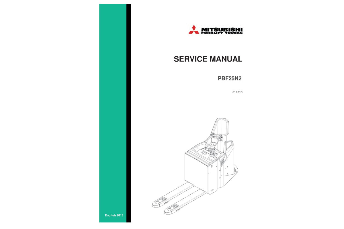



Illustrated factory set of Service Manuals for Mitsubishi Pallet Trucks Models PBF25N2.
This manuals will assist you in diagnosing, analyses, testing, repair, repairing, and troubleshooting for your pallet truck.
You can use a Windows, Mac, or Android device to view this manuals. You only need to have a PDF reader installed.
Covered Models:
PBF25N2
The manual comprises 9 documents, including four Service Manuals, three Technical Manuals, and two Wiring Diagrams
1. Service Manual: ZAPI EPS-AC0 (Zapi_EPS-AC0)
Format: PDF, 95 pages
Language: English
Table of Contents:
INTRODUCTION
SPECIFICATION
Technical specifications
Block diagram
Electrical specifications
Mechanical specifications
FUNCTIONS OF THE EPS-AC0
Manual Mode Steering
Automatic Centering
Operational features
Diagnosis
SYSTEM COMPONENTS
Steering Motor
Gear Box and total reduction ratio
Eps-ac0 controller
Sensor in the steering handle
Feedback sensors
AUTC MODE
CONNECTING DIAGRAMS
Power Connecting Diagram
EPS-AC0 Stepper Motor diagram
EPS-AC0 Twin pot diagram
CONNECTIONS: SUGGESTIONS AND CAUTIONS
Stepper Motor connections
Twin pot connections
Encoder connections
Feedback pot connections
Digital Inputs connections
Safety contacts
Motor thermal sensor connections
INSTALLATION: SUGGESTIONS AND CAUTIONS
Thermal consideration
General suggestion
Connection cables
Fuses
Contactors
Installation of a CAN Communication System
Wiring: I/O connections
Safety features
EMC
Fighting the dither
DESCRIPTION OF THE CONNECTORS
Connectors of the logic
Description of power connections
INSTALLATION PROCEDURE
Twin Pot with Encoder and Feedback pot: one shot installation procedure .4
Twin Pot with Encoder, Straight Ahead Switch and Feedback pot: one shot installa
procedure
Stepper Motor with Encoder and Feedback pot: one shot installation procedure
Stepper Motor with Encoder and Toggle Switch(es): one shot installation procedure
SETTING THE EPS-AC0
Complete set-up description
Quick set-up
PROGRAMMAING & ADJUSTMENTS USING DIGITAL CONSOLE.5
Adjustments via console
Description of console (hand set) & connection
Description of standard console menu
Function configuration
OTHER FUNCTIONS
Acquiring the Motor resistance
Alignment at the rest position
Straight ahead steering numbness
Special Debugging and Troubleshooting system
EPS-AC0 ALARMS LIST
Main menu “ALARMS” list
CAN BUS “ALARMS” List
RECOMMENDED SPARE PARTS
PERIODIC MAINTENANCE TO BE REPEATED AT TIMES INDICATED
Testing the faulty detection circuitry .
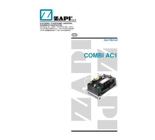
2. Service Manual: ZAPI COMBI AC1 Controller (ZAPI_COMBI_AC1)
Format: PDF, 84 pages
Language: English
Table of Contents:
INTRODUCTION
SPECIFICATION
Technical specifications
Block diagrams
SPECIFICATION FOR THE INPUT DEVICES FILLING UP THE INSTALLATION KIT
Digital inputs
Analog unit
Other analog control unit
Analog motor thermal sensor input
Speed feedback
INSTALLATION HINTS
Material overview
Installation of the hardware
Protection and safety features
EMC
Various suggestions
OPERATIONAL FEATURES
Diagnosis
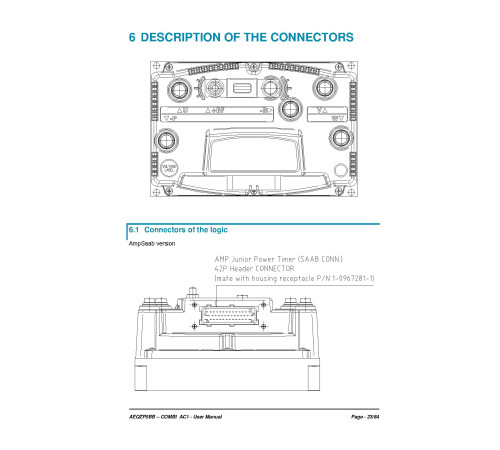
DESCRIPTION OF THE CONNECTORS
Connectors of the logic
Description of power connections
DRAWINGS
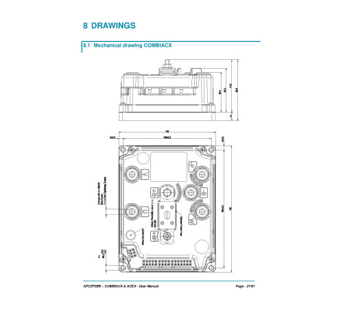
Mechanical drawing
Connection drawing
ONE SHOT INSTALLATION PROCEDURE
Sequence for Ac Inverter traction setting
PROGRAMMING & ADJUSTMENTS USING DIGITAL CONSOLE
Adjustments via console
Description of console (hand set) & connection
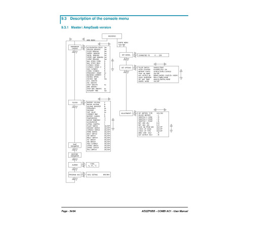
Description of the console menu
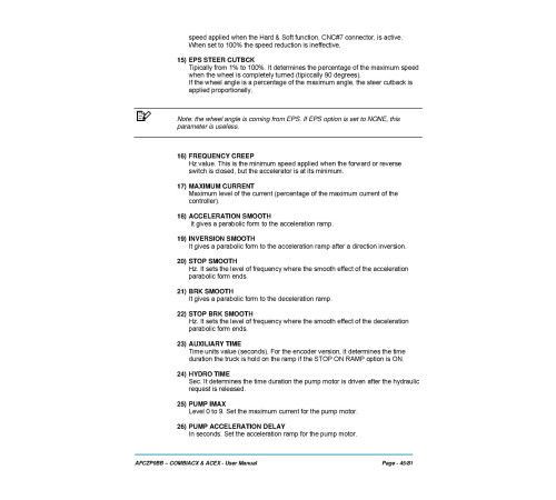
Function configuration (MASTER)
Function configuration (SLAVE)
OTHER FUNCTIONS
Description of console “SAVE” function
Description of console “RESTORE” function
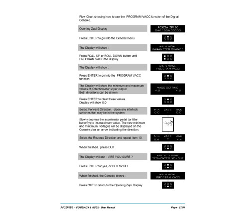
Description of console “PROGRAM VACC” function
Description of the throttle regulation
Description of the battery charge detection setting
COMBI AC1 ALARMS LIST
Faults diagnostic system
Master microcontroller alarms overview
Analysis and troubleshooting of Master microcontroller alarms
Master warnings overview
Analysis and troubleshooting of Master warnings
Slave alarms overview
Analysis and troubleshooting of Slave alarms
Slave warnings overview
Analysis and troubleshooting of Slave warnings
RECOMMENDED SPARE PARTS
PERIODIC MAINTENANCE TO BE REPEATED AT TIMES INDICATED.
3. Service Manual: ZAPI COMBI ACX & ACEX Controller (ZAPI_COMBI_ACX-ACEX)
Format: PDF, 81 pages
Language: English
Table of Contents:
INTRODUCTION
SPECIFICATION
Technical specifications COMBIACX / ACEX
Technical specifications COMBIACX Power / ACEX Power
Block diagrams
SPECIFICATION FOR THE INPUT DEVICES FILLING UP THE INSTALLATION KIT
Digital inputs
Analog unit
Other analogue control unit
Analog motor thermal sensor input
Speed feedback
INSTALLATION HINTS
Material overview
Installation of the hardware
Protection and safety features
EMC
Various suggestions
OPERATIONAL FEATURES
Diagnosis
DESCRIPTION OF THE CONNECTORS
Connectors of the logic
DESCRIPTION OF POWER CONNECTIONS
DRAWINGS
Mechanical drawing COMBIACX
Mechanical drawing ACEX
Connection drawing COMBIACX
Connection drawing ACEX
ONE SHOT INSTALLATION PROCEDURE
Sequence for Ac Inverter traction setting
PROGRAMMING & ADJUSTMENTS USING DIGITAL CONSOLE
Adjustments via console
Description of console (hand set) & connection
Description of the console menu
Function configuration
OTHER FUNCTIONS
Description of console “SAVE” function
Description of console “RESTORE” function
Description of console “PROGRAM VACC” function
Description of the throttle regulation
Description of the battery charge detection setting
COMBIACX /ACEX ALARMS LIST
Faults diagnostic system
Alarms overview
Warnings overview
Analysis and troubleshooting of warnings
RECOMMENDED SPARE PARTS
PERIODIC MAINTENANCE TO BE REPEATED AT TIMES INDICATED.
4. Service Manual (SM-618015-B_14)
Format: PDF, 226 pages
Language: English
Table of Contents:
Foreword
How to read this manual
Safety-related signs
Symbols and abbreviations
Units
Safety instructions
Service area safety
Personal safety
Work safety
General information
Truck model covered by this manual
Identification plates on the truck
Overview of the truck
Mechanical maintenance
Lifting points
Transportation
Ordering spare parts
Opening the covers
Removing the side plate
Removing the plastic covers of the backrest
Removing the operator’s platform
Transmission gear
Bogie bearing
Traction wheel
Load wheels
Lifting system and fork carriage
Castor wheels
Castor wheel suspension
Disassembly of the drive unit suspension
Steering wheel
Electrical operation
Using the schematic diagram
Power source
Safety circuit (emergency stop button)
Key switch
Traction
AC motor operation
Electrical steering
Battery maintenance
Safety regulations concerning the handling of lead-acid batteries
Battery maintenance
Recharging the battery
Measuring the battery'sspecific gravity
Replacing the battery
Electric system maintenance
Electric panel
Truck connector
Motor compartment
Pump motor
Sensors
Switches and buttons
Horn
Wiring harnesses and cables
Electric system adjustments and measurements
Adjusting the electrically powered steering
Insulation resistance test
Hydraulic operation
Hydraulic symbols
Hydraulic oil recommendations
Maintenance points of the hydraulic system
Hydraulic aggregate
Replacing the hydraulic cylinder
TruckTool Diagnostics
Parameter descriptions
Traction controller
Pump controller
Steering controller
Alarm codes
Traction controller
Pump controller
Steering controller
Service data
Special tightening torques
Tightening torque for standard bolts and nuts
Maintenance check list
Lubrication
Special tools
Options
Pallet entry / exit rollers
Load support
Accessory rack
Voltage converter
Battery lock sensor
Battery connector
Charger connector
Quick battery replacement
Technical specification
Index
APPENDIX A: Stickers.
5. Technical Manual: Parameters for Traction Controller (PA-PBF25N2_TR)
Format: PDF, 7 pages
Language: English
6. Technical Manual: Parameters for Pump Controller (PA-PBF25N2_PU)
Format: PDF, 4 pages
Language: English
7. Technical Manual: Parameters for Steering Controller (PA-PBF25N2_EPS)
Format: PDF, 3 pages
Language: English
8. Wiring Diagram (EL-TS1370000_RevC)
Format: PDF, 9 pages
Language: English
Table of Contents:
POWER SUPPLY 24 V
MAINCIRCUITS
DRIVE CIRCUIT
DRIVE CIRCUIT 180 STEERING
STEERING CIRCUIT
CAN-BUS AND DISPLAY
OUTPUTS
COLD STORAGE, AUX. DEVICES
ABBOT 2
9. Wiring Diagram (EL-TS1150908_RevE)
Language: English
Included
Service Manual
4Technical Manual
3Wiring Diagram
2Reviews: 0
There are no reviews for this product.
Questions: 0
No questions about this product.
Похожие товары

