

$20.00
Fault Codes List
1Service Manual
3Engine Technical Manual
1Wiring Diagram
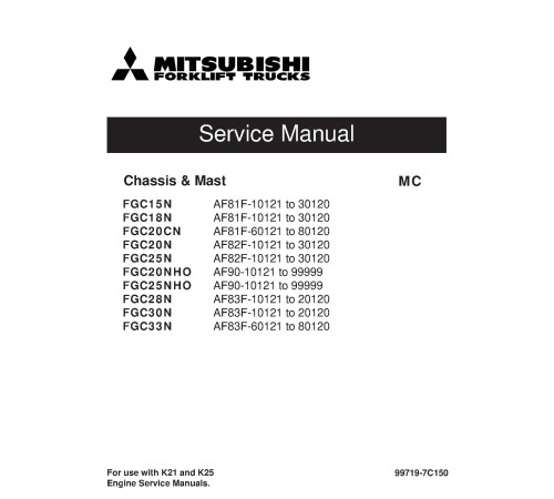
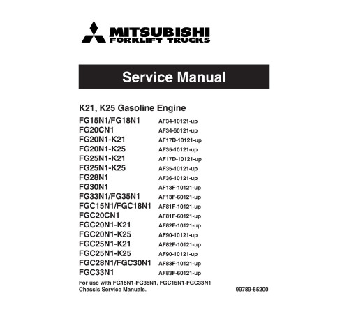
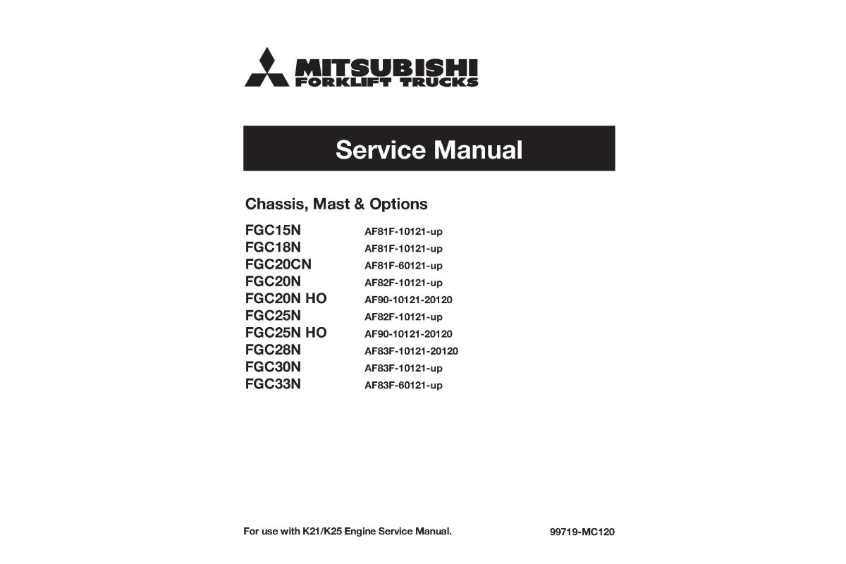
1Illustrated factory set of Service Manuals for Mitsubishi s Models FGC15N (AF81F-10121-30120), FGC18N (AF81F-10121-30120), FGC20CN (AF81F-60121-80120), FGC20N (AF82F-10121-30120), FGC25N (AF82F-10121-30120), FGC20NHO (AF90-10121-99999), FGC25NHO (AF90-10121-99999), FGC28N (AF83F-10121-20120), FGC30N (AF83F-10121-20120) and FGC33N (AF83F-60121-80120).
This manuals will assist you in determining a malfunction using a fault code, diagnosing, analyses, testing, repair, repairing engine, and troubleshooting for your .
You can use a Windows, Mac, or Android device to view this manuals. You only need to have a PDF reader installed.
Covered Models:
FGC15N (AF81F-10121-30120)
FGC18N (AF81F-10121-30120)
FGC20CN (AF81F-60121-80120)
FGC20N (AF82F-10121-30120)
FGC25N (AF82F-10121-30120)
FGC20NHO (AF90-10121-99999)
FGC25NHO (AF90-10121-99999)
FGC28N (AF83F-10121-20120)
FGC30N (AF83F-10121-20120)
FGC33N (AF83F-60121-80120)
The manual comprises 6 documents, including the Fault Codes List, three Service Manuals, Engine Technical Manual, and Wiring Diagram
1. Fault Codes List (REF-18-0008M_69904)
Format: PDF, 13 pages
Language: English
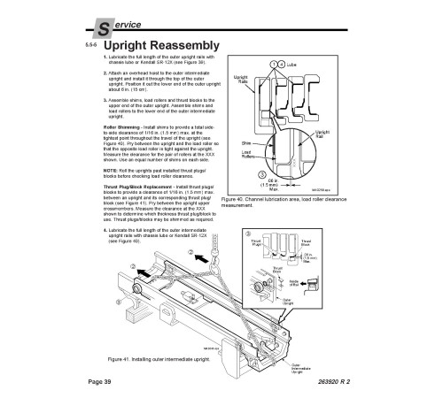
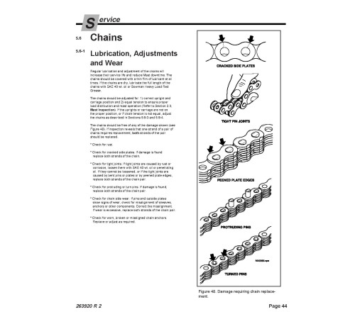
2. Service Manual: 35DV/45DV/55DV-MQ Mast (SM-LTI-263920-Mast)
Format: PDF, 48 pages
Language: English
3. Service Manual: Chassis & Mast (SM-99719-7C150_A0714)
Format: PDF, 544 pages
Language: English
Publication Date: 01 Jul 2014
Table of Contents:
GENERAL INFORMATION
Model View
Truck Models Covered
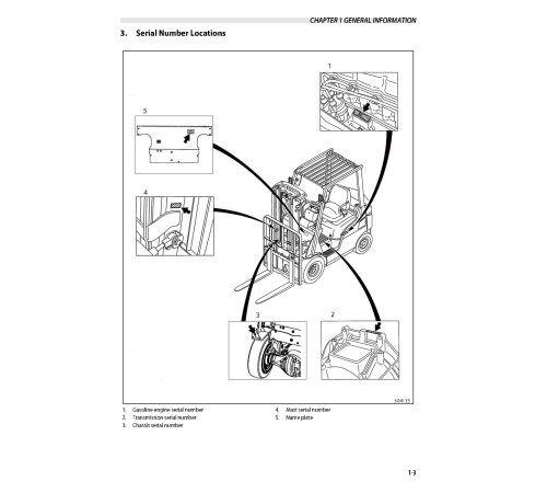
Serial Number Locations
Dimensions
Technical Data
COOLING SYSTEM
Specification
Structure
Removing Fan Belt
Installing Fan Belt
Inspecting and Adjusting Cooling System
ELECTRICAL SYSTEM
Electrical Components and Wiring Outline
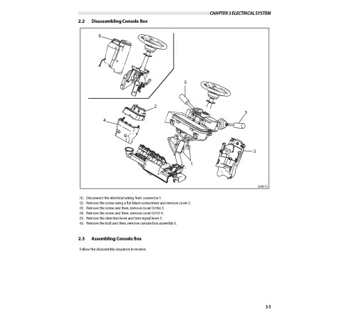
Console Box
Meter Panel
Main Electrical Components
Battery and Maintenance
Wire Color
Troubleshooting
Fuel Pressure Sensor Harness
Wiring Harness Service Parts
Electrical Wiring Diagram
CONTROLLER
Outline
Main Functions of Controllers
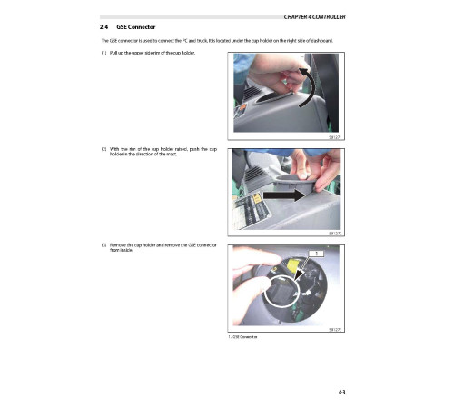
Service Tool
Mast Interlock System
Driving Interlock System
Seat Belt Warning Light
Parking Brake Warning Buzzer and Light
Harness Codes
Controller Output Details
Truck Status Display and Troubleshooting
Common Diagnostic Codes
POWER TRAIN
Removing and Installing Engine and Transmission Assembly
POWERSHIFT TRANSMISSION
Structure
Removing Transmission
Installing Transmission
Disassembling Control Valve
Inspection and Repair After Disassembling Control Valve
Assembling Control Valve
Disassembling Input Shaft Assembly
Inspection and Repair After Disassembling Input Shaft Assembly
Disassembling Oil Pump Assembly
Inspection and Repair After Disassembling Oil Pump Assembly
Assembling Oil Pump
Inspection and Adjustment
Troubleshooting
Tightening Torque
Service Data
FRONT AXLE AND REDUCTION DIFFERENTIAL
Structure
Removing and Installing Front Wheels
Removing Front Axle
Disassembling and Assembling Front Axle
Removing and Installing Reduction Differential
Disassembling and Assembling Reduction Differential
Disassembling and Assembling Reduction Differential
Troubleshooting
Service Data
REAR AXLE
Structure
Removing Rear Wheels
Installing Rear Wheels
Removing Rear Wheels and Rear Axle Assembly
Installing Rear Wheels
Disassembling Wheel Hub
Inspection and Repair After Disassembly
Assembling Wheel Hub
Disassembling Knuckle (King Pin)
Inspection and Repair After Disassembling Knuckle (King Pin)
Assembling Knuckle (King Pin)
Removing Steering Cylinder
Inspection and Repair After Disassembling Steering Cylinder
Assembling Steering Cylinder
Disassembling and Assembling Tie Rod
Assembling Tie Rod
Troubleshooting
Service Data
BRAKE SYSTEM
Structure of Brake System
Structure of Wheel Brakes
Disassembling Master Cylinder
Inspection and Repair After Disassembling Master Cylinder
Assembling Master Cylinder
Disassembling Wheel Brakes
Inspection After Disassembling Wheel Brakes
Assembling Wheel Brakes
Assembling Wheel Cylinder
Inspection and Repair After Disassembling Wheel Cylinder
Assembling Wheel Cylinder
Inspecting and Adjusting Brake System
Troubleshooting
Service Data
STEERING SYSTEM
Structure and Function
Disassembling and Assembling Pipes and Hoses
Disassembling Steering Wheel and Steering Valve
Installation
Removing Steering Valve
Installing Steering Valve
Disassembling Tilt Lock Lever
Assembling Tilt Lock Lever
Disassembling Steering Valve
Inspection After Disassembly
Assembling Steering Valve
Troubleshooting
Service Data
HYDRAULIC SYSTEM
Structure
Removing Hydraulic Pump
Installing Hydraulic Pump
Disassembling Hydraulic Pump
Inspection and Repair After Disassembling Hydraulic Pump
Assembling Hydraulic Pump
Inspection and Adjustment After Assembling Hydraulic Pump
Removing Lift Cylinders (Simplex Mast)
Installing Lift Cylinder (Simplex Mast)
Removing Lift Cylinder (Duplex and Triplex Mast)
Installing Lift Cylinder (Duplex and Triplex Mast)
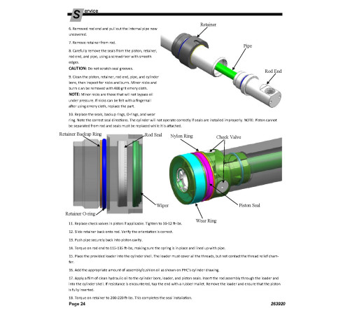
Disassembling Lift Cylinder (First Lift Cylinder for Duplex Mast and Triplex Mast)
Inspection After Disassembly (First Lift Cylinder for Duplex Mast and Triplex Mast)
Assembling Lift Cylinder (First Lift Cylinder for Duplex Mast and Triplex Mast)
Disassembling Lift Cylinder (Second Cylinder for Simplex Mast and Triplex Mast)
Inspection After Disassembling Lift Cylinder (Second Cylinder for Simplex Mast and Triplex Mast)
Assembling Lift Cylinder (Second Cylinder for Simplex Mast and Triplex Mast)
Disassembling Lift Cylinder (Second Lift Cylinder for Duplex Mast)
Inspection After Disassembling Lift Cylinder (Second Lift Cylinder for Duplex Mast)
Assembling Lift Cylinder (Second Lift Cylinder for Duplex Mast)
Removing Tilt Cylinder
Installing Tilt Cylinder
Disassembling Tilt Cylinder
Assembling Tilt Cylinder
Piping
Removing Suction Strainer and Return Filter
Inspecting Suction Strainer and Return Filter
Installing Suction Strainer and Return Filter
Hydraulic System Adjustment
Troubleshooting
Service Data
MC Control Valve
Removing MC Control Valve
Installing MC Control Valve
Disassembly Sequence of Valve of Inlet Cover Section
Disassembly Sequence of Combination Section (Lift Valve)
Disassembly Sequence of Combination Section (Tilt Valve)
Disassembly Sequence of End Cover Section (Unloader Valve)
Inspection and Repair After Disassembling MC Control Valve
Assembling MC Control Valve
MAST AND FORKS
Simplex Mast
Duplex Mast
Triplex Mast
SERVICE DATA
Maintenance Schedule
Tightening Torques for Standard Bolts and Nuts
Periodic Replacement Parts
Lubrication Instructions
Special tools
APPENDIX
Sulfur Smell from the Exhaust System
High Speed Cooling (Option)
Corrugated Square Fin Cove Option
Information on the Foot Directional Control System (Option)
Ground Speed Control or Travel Speed Limit Option
DOT-Lok MPE Installation and Programming
Propane Fuel Tank Basics
Heavy Duty Upper Wear Pad Kit
Back cover
Rear cover
4. Service Manual: Chassis, Mast & Options (SM-99719-MC120)
Format: PDF, 343 pages
Language: English
Table of Contents:
FOREWORD
GROUP INDEX
GENERAL INFORMATION
COOLING SYSTEM
ELECTRICAL SYSTEM
Electrical Schematic
CONTROLLERS
POWER TRAIN
POWERSHIFT TRANSMISSION
FRONT AXLE
REDUCTION DIFFERENTIAL
REAR AXLE
BRAKE SYSTEM
STEERING SYSTEM
HYDRAULIC SYSTEM
MAST AND FORKS
SERVICE DATA
5. Engine Technical Manual: K21, K25 Gasoline Engine (EN-99789-55200_K21-K25_A07)
Format: PDF, 208 pages
Language: English
Table of Contents:
How to use this manual
Description
Definition of Terms
Definition of Units
Description
Precautions for safety and quality
Reduction of Risk Operation
Correct Operation
Precautions for Radio Equipment Installation
Precautions
Precautions in Draining Engine Coolant
Precautions for Disconnecting Fuel Piping
Precautions for Removing and Disassembling
Precautions for Inspection, Correction, and Replacement
Precautions for Assembly and Installation
Parts Requiring Angle Tightening
Caution for Use of Power Tools
Precautions for Liquid Gasket Application
Tightening torque
Standard Bolt Tightening Torque
Engine Part Tightening Torque
Special Service Tools
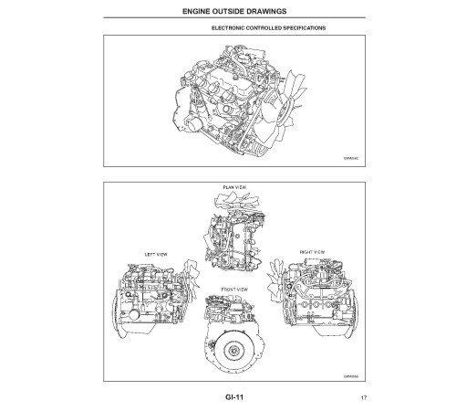
Engine outside drawings
MAIN SPECIFICATIONS
Standard and repair limit
STAMPED LOCATION OF ENGINE NO.
Trouble diagnosis
Engine Adjustment
Engine LPG Fuel System
Engine maintenance
Specifications
Tightening Torque
Maintenance Schedule
Oil and Grease, and Capacity
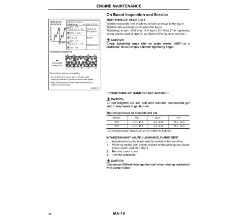
On Board Inspection and Service
Specifications
Tightening torque
Trouble diagnosis
ENGINE INSPECTION AND ADJUSTMENT
Engine Body Related
Ignition and Fuel Systems
SERVICE DATA AND SPECI FICATIONS (SDS)
Electronic Control System Specifications
Precautions
Precautions for Draining Engine Coolant
Precautions for Disconnecting Fuel Piping
Precautions for Removing and Disassembling
Precautions for Inspection, Correction, and Replacement
Precautions for Assembly and Installation
Parts Requiring Angle Tightening
Caution for Use of Power Tools
Precautions for Liquid Gasket Application
ENGINE OUTSIDE DRAWINGS
MAIN SPECIFICATIONS
ADJUSTMENT value
Tightening torque
Standard Bolt Tightening Torque
Engine Part Tightening Torque
Trouble diagnosis
Special Service Tools
Removal and installation of engine
Removal
Installation
Inspection
Engine service
Engine Disassembly
Inspection and Correction
Engine Assembly
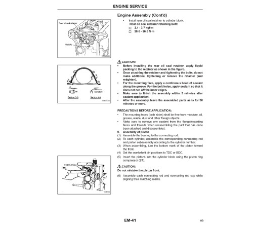
Engine Assembly (Cont’d)
Precautions
On Board Diagnostic (OBD) System of Engine
Precaution
Preparation
preparation
Special Service Tools
Description
Description
trouble diagnosis
Component Parts Location
ECM Component
Circuit Diagram
ECM Terminal
Trouble Diagnosis
How to Proceed with Trouble Diagnosis
Diagnosis Chart by Symptom
Description
Fail-Safe Function
Table of DTC
Service Tool
Self-Diagnosis Function (Without Service tool)
ECM Input/Output Monitor
ECM Active Test
Basic inspection
Inspection of Idle Speed and Ignition Timing
Throttle Valve Closed Position Learning and Idle Air Volume Learning
Accelerator Pedal Released Position Learning
Fuel Pressure Inspection
Fuel Pressure Release
COMPONENT PARTS INSPECTION
Crankshaft Position Sensor (POS)
Camshaft Position Sensor (PHASE)
Mass Air Flow Sensor
Engine Coolant Temperature Sensor
Throttle Position Sensor 1, 2 (Electric throttle control actuator assembly)
Component Parts Inspection
Accelerator Pedal Position Sensors 1, 2 (Accelerator work unit)
Intake Air Temperature Sensor (Joined with mass air flow sensor)
Stop Lamp Switch
Spark Plug
Ignition Coil
Injector
Fuel Pump
Electric Throttle Control Motor (Electric throttle control actuator assembly)
Heated Oxygen Sensor
LPG Injector
LPG Assistance Injector
PTC Heater (Integrated with vaporizer)
pcv gas recirculation devi
System Diagram
Component Parts Inspection
ECM components
Removal and Installation
Lubrication system
Specifications
Adjustment Value
Oil Pressure
Tightening Torque
Trouble Diagnosis
Lubrication Schematic Diagram
Oil Pump
Engine coolant system
Specifications
Adjustment Value
Tightening Torque
Trouble Diagnosis
Cooling System Configuration
Water Pump
Thermostat
Emission control system
ENGINE OUTSIDE DRAWINGS
SYSTEM DIAGRAM
UNIT LAYOUT
LPG FUEL SYSTEM TROUBLE DIAGNOSIS
DISASSEMBLY AND ASSEMBLY OF FUEL SYSTEM
Removal and Installation of Electronic Control Throttle Assembly
Removal and Installation of Gasoline Fuel Injector (Electronic Controlled Gasoline and Combined Use)
LPG device (Specifications for LPG and combined use)
Vaporizer Mechanism and Operation
DISASSEMBLY AND ASSEMBLY OF INJECTOR HOLDER
LPG Fuel Injector
LPG Assist Fuel Injector
LPG Fuel Pressure Sensor
Relief Valve (2 Relief Valves)
DISASSEMBLY AND ASSEMBLY OF VAPORIZER
Tar drain, Removal and Installation of Vaporizer
Adjustment value
Trouble diagnosis
Starter motor
Starter Motor Specifications
Component Parts Location
Overhaul
Assembly Inspection
ALTERNATOR
Components of Alternator
Disassembly
Inspection
6. Wiring Diagram (EL-99719-7C140s)
Format: PDF, 2 pages
Language: English
Included
Fault Codes List
1Service Manual
3Engine Technical Manual
1Wiring Diagram
1Reviews: 0
There are no reviews for this product.
Questions: 0
No questions about this product.
Похожие товары


