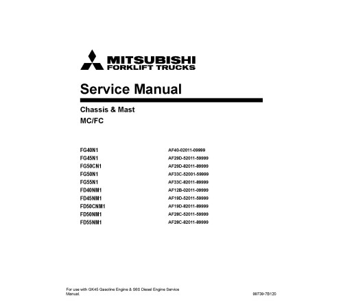
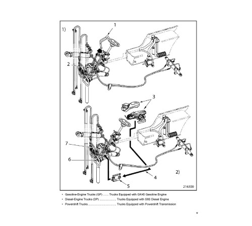
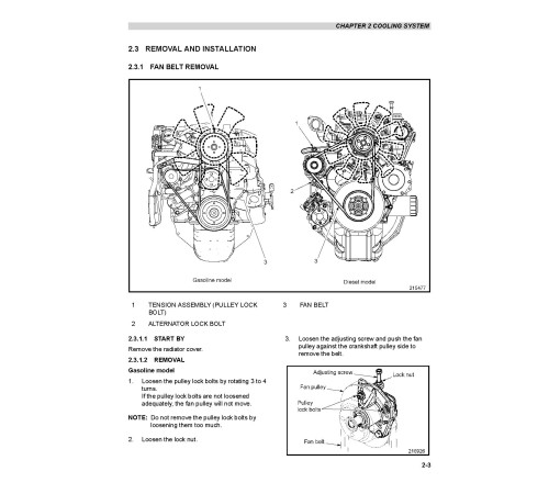
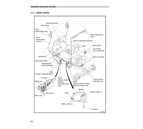


Illustrated factory set of Service Manuals for Mitsubishi Diesel Forklift Trucks Models FD40NM1 (AF12B-02011-09999), FD45NM1 (AF19D-52011-59999), FD50CNM1 (AF19D-82011-89999), FD50NM1 (AF28C-52011-59999) and FD55NM1 (AF28C-82011-89999).
This manuals will assist you in diagnosing, analyses, testing, repair, and repairing engine for your diesel forklift truck.
You can use a Windows, Mac, or Android device to view this manuals. You only need to have a PDF reader installed.
Covered Models:
FD40NM1 (AF12B-02011-09999)
FD45NM1 (AF19D-52011-59999)
FD50CNM1 (AF19D-82011-89999)
FD50NM1 (AF28C-52011-59999)
FD55NM1 (AF28C-82011-89999)
The manual comprises 4 documents, including two Service Manuals, the Engine Technical Manual, and Special Instruction
1. Service Manual (SM-99739-7B120_22)
Format: PDF, 640 pages
Language: English
Table of Contents:
GENERAL INFORMATION
Model View
Forklift Truck Models Covered
Serial Number Locations
Dimensions
Technical Data
Performance
COOLING SYSTEM
Specifications
Structure
Removal and Installation
Inspection and Adjustment
Troubleshooting
ELECTRIC SYSTEM
Chassis Electrical Devices Wiring Outline
Structure
Console Box
Battery Maintenance
Instrument Panel
Wire Color
Troubleshooting
CONTROLLERS
Outline
Main Functions of Controllers
Service Tool Functions
Mast Interlock System
Driving Interlock System
Seat Belt Warning Lamp
Parking Brake Warning Buzzer and Lamp
Harness Code List
Controller Output Details
Error Codes and Troubleshooting
Locations of Sensors and Switches
POWER TRAIN
Removal and Installation (MC Models)
Removal and Installation (FC Models)
Removal and Installation (Wet disc brake)
Service Data
POWERSHIFT TRANSMISSION
Structure
Removal and Installation
Transmission Exterior Parts
Torque Converter
Transmission
F2 Clutch Pack Assembly
F1 Clutch Pack Assembly
R1 Clutch Pack Assembly
Parking Brake Assembly
Gear Pump Assembly
Control Valve
Main Regulator Valve
Inspection and Adjustment
Troubleshooting
Service Data
FRONT AXLE AND REDUCTION DIFFERENTIAL
Specifications
Structure
Removal and Installation
Disassembly and Reassembly
REAR AXLE
Structure and Functions
Removal and Installation
Disassembly and Reassembly
Troubleshooting
Service Data
BRAKE SYSTEM
Structure
Disassembly and Reassembly
Inspection and Adjustment
Troubleshooting
Service Data
STEERING SYSTEM
Structure and Functions
Disassembly and Reassembly
Steering Valve
Troubleshooting
Service Data
STC (Snap-to-Connect)
HYDRAULIC SYSTEM
Structure and Functions
Disassembly and Reassembly
Inspection and Adjustment
Troubleshooting
Service Data
MC Control Valve
FC Control Valve
Hydraulic Oil Tank Breather
MAST AND FORKS
Simplex Mast
Structure and Functions
Removal and Installation
Disassembly and Reassembly
Removal and Installation of Mast Rollers and Strips without Removing
Inspection and Adjustment (Simplex Mast)
Troubleshooting (Simplex Mast)
Service Data (Simplex Mast)
Duplex Mast
Structure and Functions
Removal and Installation
Disassembly and Reassembly
Removal and Installation of Mast Rollers and Strips without Removing
Inspection and Adjustment (Duplex Mast)
Troubleshooting (Duplex Mast)
Service Data (Duplex Mast)
Triplex Mast
Structure and Functions
Removal and Installation
Disassembly and Reassembly
Removal and Installation of Mast Rollers and Strips without Removing
Inspection and Adjustment (Triplex Mast)
Troubleshooting (Triplex Mast)
Service Data (Triplex Mast)
SERVICE DATA
Maintenance Schedule
Tightening Torque for Standard Bolts and Nuts
Periodic Inspection Parts
Lubrication Instructions
Special Service Tools
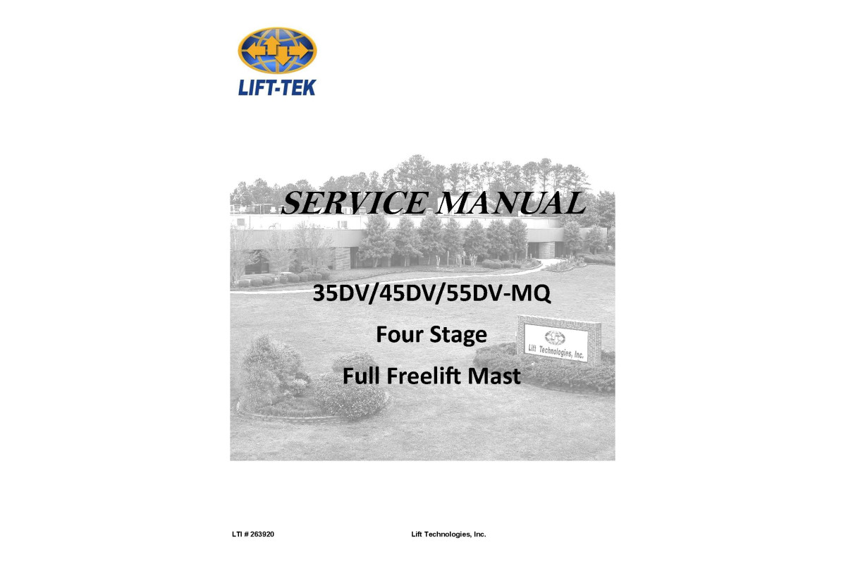
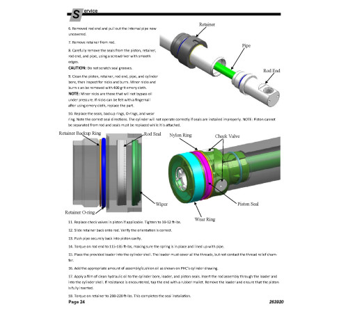
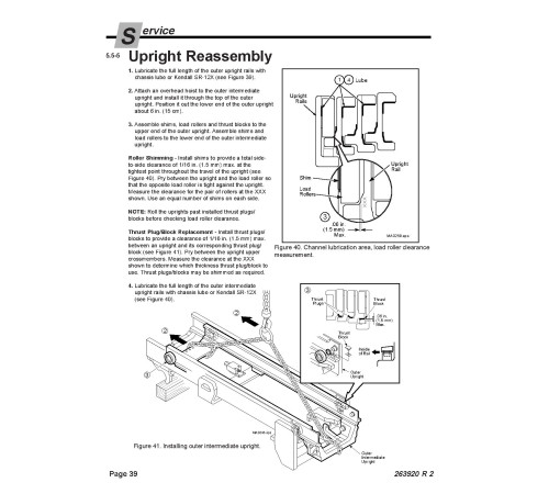
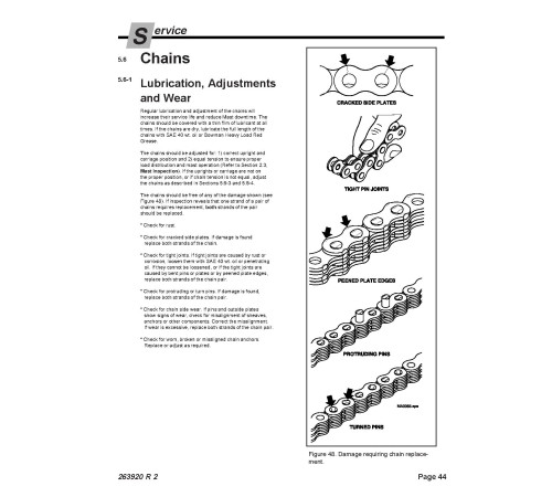
2. Service Manual: 35DV/45DV/55DV-MQ Mast (SM-LTI-263920-Mast)
Format: PDF, 48 pages
Language: English
3. Engine Technical Manual: S6S Diesel Engine (EN-99739-12110_S6S_0313)
Format: PDF, 206 pages
Language: English
Table of Contents:
GENERAL
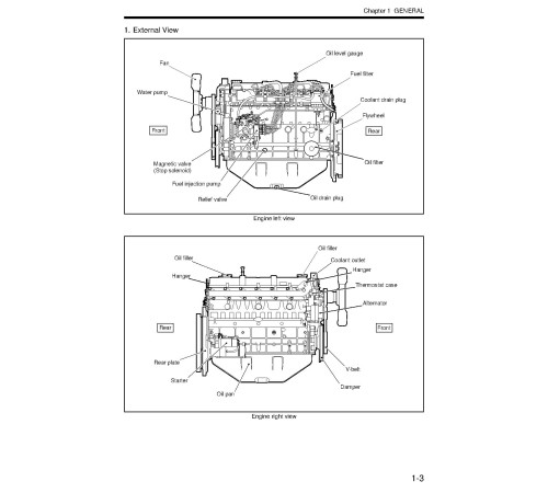
External View
System flow diagrams
Engine serial number location
Main specifications
SERVICE DATA
Maintenance service data
Tightening torque table
SERVICE TOOLS
Special tools
OVERHAUL INSTRUCTIONS
Determining overhaul timing
Compression pressure - Measure
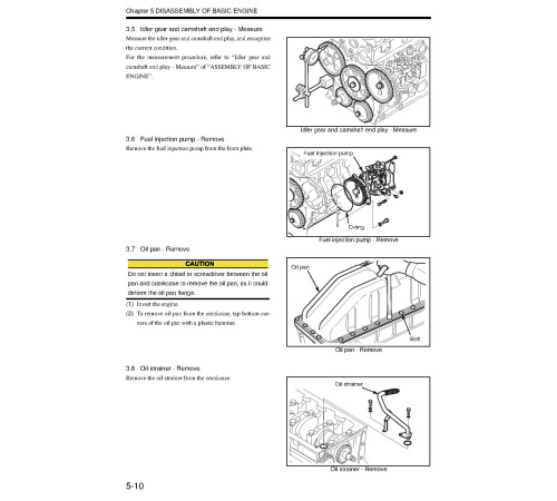
DISASSEMBLY OF BASIC ENGINE
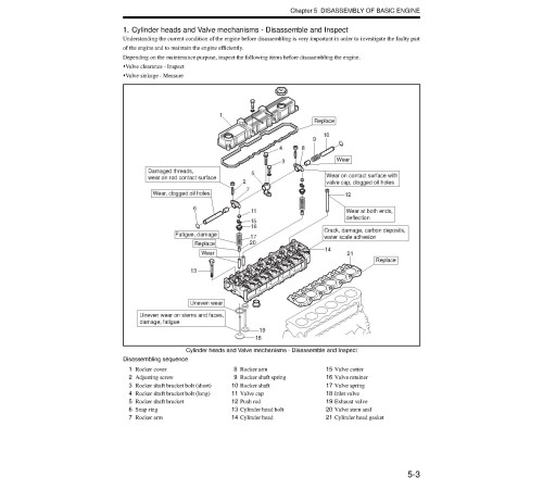
Cylinder heads and Valve mechanisms - Disassemble and Inspect
Rear equipment - Disassemble and Inspect
Front equipment - Disassemble and Inspect
Piston, Connecting rod, Crankshaft and Crankcase - Disassemble and Inspect
INSPECTION AND REPAIR OF BASIC ENGINE
Cylinder head and Valve mechanism - Inspect and Repair
Rear equipment - Inspect and Repair
Front equipment - Inspect and Repair
Piston and Connecting rod - Inspect and Repair
Crankcase and Crankshaft - Inspect and Repair
ASSEMBLY OF BASIC ENGINE
Piston, Connecting rod, Crankshaft and Crankcase - Assemble
Front equipment - Assemble
Rear equipment - Assemble
Cylinder head and Valve mechanism - Assemble
FUEL SYSTEM
Fuel system - Remove
Fuel system - Disassemble, Inspect and Assemble
Fuel system - Install
LUBRICATION SYSTEM
Lubrication system - Remove
Lubrication system - Disassemble, Inspect and Assemble
Lubrication system - Install
COOLING SYSTEM
Cooling system - Remove
Cooling system - Disassemble, Inspect and Assemble
Cooling system - Install
INLET AND EXHAUST SYSTEMS
Inlet and exhaust systems - Remove
Inlet and exhaust systems - Disassemble, Inspect and Assemble
Inlet and exhaust systems - Install
ELECTRICAL SYSTEM
Electrical system - Remove and Inspect
Electrical system - Disassemble, Inspect and Assemble
Electrical system - Install
ADJUSTMENT AND OPERATION
Engine - Adjust
Break-in operation
Performance test
TECHNICAL PUBLICATIONS FEEDBACK
Back cover
Rear cover
4. Special Instruction (M16009 R3_56060)
Format: PDF, 252 pages
Language: English
Included
Service Manual
2Engine Technical Manual
1Special Instruction
1Reviews: 0
There are no reviews for this product.
Questions: 0
No questions about this product.
Похожие товары

