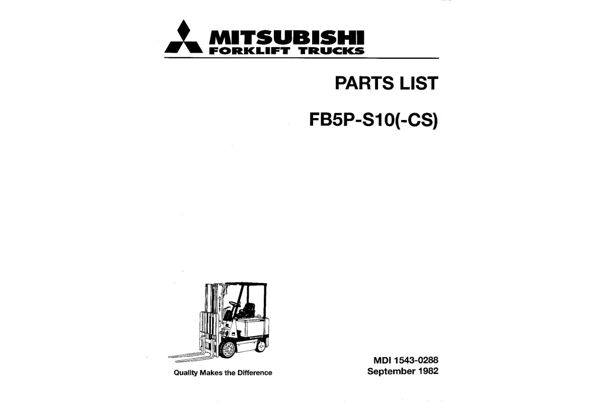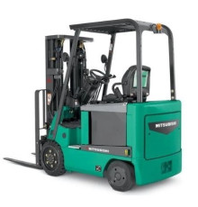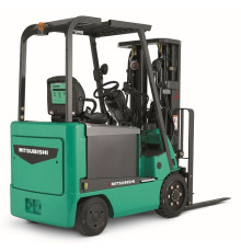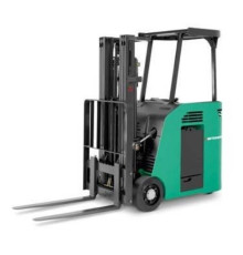


Illustrated factory set of Service Manuals for Mitsubishi Electric Forklift Trucks Models FB5P-S10 (NYK).
This manuals will assist you in troubleshooting, and finding spare parts for your electric forklift truck.
You can use a Windows, Mac, or Android device to view this manuals. You only need to have a PDF reader installed.
Covered Models:
FB5P-S10 (NYK)
The manual comprises 3 documents, including two Wiring Diagrams, and the Parts Catalog
1. Wiring Diagram (WM-MDI-3301-1184T_1080)
Format: PDF, 62 pages
Language: English
Table of Contents:
OVERHEAD GUARD AND BATTERY
Removing the Overhead guard
Removing the battery
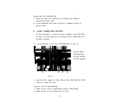
LOAD HANDLING DEVICE
Disassembling of the fork complete
Removing the high pressure hose of cylinder assembly
Removing the Mast Assembly.
Removing the Lift Bracket Assembly and its
Disassembling
Removing Chain Sheeve
Removing the lift cylinder assembly
Disassembling the Cylinder Assembly
Disassembling the Mast Assembly
DRIVE UNIT
For removing the brake linkage
Disassembling the Drive Unit Assembly
Disassembling the Drive Unit
TYRES
For disassembling and reassembling the drive tyres4-2. Wheel Rim
STEERING LINKAGE
Disassembling the Steering Assembly
Disassembling the Gear Box Assembly
Adjust the Chain
Disassembling the Rear Axle Assembly
Adjustment Microswitch
BRAKE UNIT
Disassembling the Brake Assembly
Adjusting the Brake
Disassembling the linkage Assembly
HYDRAULIC PRESSURE UNIT
Disassembling the Tilt Cylinder Assembly
Disassembling the Power Unit Assembly
Disassembling of Control Valve Assembly and Gear Pump Assembly
MOTOR ASSEMBLY
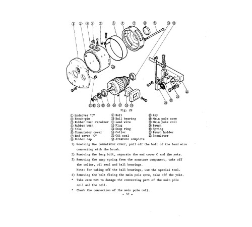
Disassembling the Motor Assembly
ACCELERATOR LINKAGE AND CONTROLLER
Remove the accelerator linkage assembly
Removing of the Controller Assembly
Disassembling of Controller Assembly
CONTACTOR UNIT
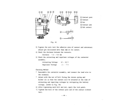
Disassembling of the Contactor Unit Assembly
Disassembling the Contactor Assembly
Disassembling the Contactor Unit Assembly
Removing the Fuse
Removing the timer components
On Adjusting the Timer
REMOVING THE RESISTOR ASSEMBLY
LEVER SWITCH ASSEMBLY
Disassembling the Lever Switch Assembly
Disassembling of Lever Switch Assembly
INDICATOR PANEL ASSEMBLY
Disassembling the Indicator Panel Assembly
Removing of Each Component Part
REMOVING THE HORN SWITCH AND HORN
CHARGER
Removing the charger assembly
Removing the Each Component Part
2. Wiring Diagram (EL-MDI-3301-1184S)
Format: PDF, 1 page
Language: English
3. Parts Catalog (PM-MDI-1543-0288_0982)
Format: PDF, 112 pages
Language: English
Table of Contents:
FRAME (1)
FRAME (2)
DRIVE (FRONT AXLE)
WHEEL BRAKE
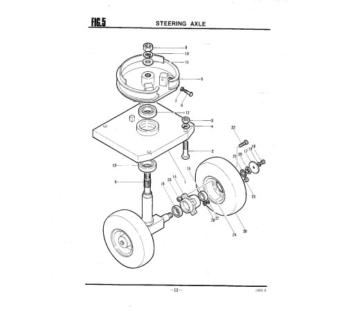
STEERING AXLE
STEERING LINKAGE
BRAKE LINKAGE
ACCELERATOR LINKAGE
POWER UNIT (1) (VALVE LINKAGE)
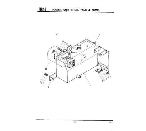
POWER UNIT (2) (OIL TANK & PUMP)
CONTROL VALVE
OIL PIPING
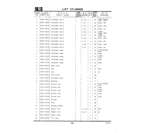
LIFT CYLINDER
MAST
CHAIN WHEEL
LIFT BRACKET
DRIVE MOTOR
CONTACTOR (1)
CONTACTOR (2)
CONTACTOR (3)
RESISTOR
ACCELERATOR (STD)
ACCELERATOR (CS)
INDICATOR PANEL
CHARGER (BULIT IN CHARGER)
CHARGER (STATIONARY
TYPE CHARGER)
DIRECTIONAL SWITCH
ELECTRIC PARTS
NAME PLATE
Included
Wiring Diagram
2Parts Catalog
1Reviews: 0
There are no reviews for this product.
Questions: 0
No questions about this product.
Похожие товары

