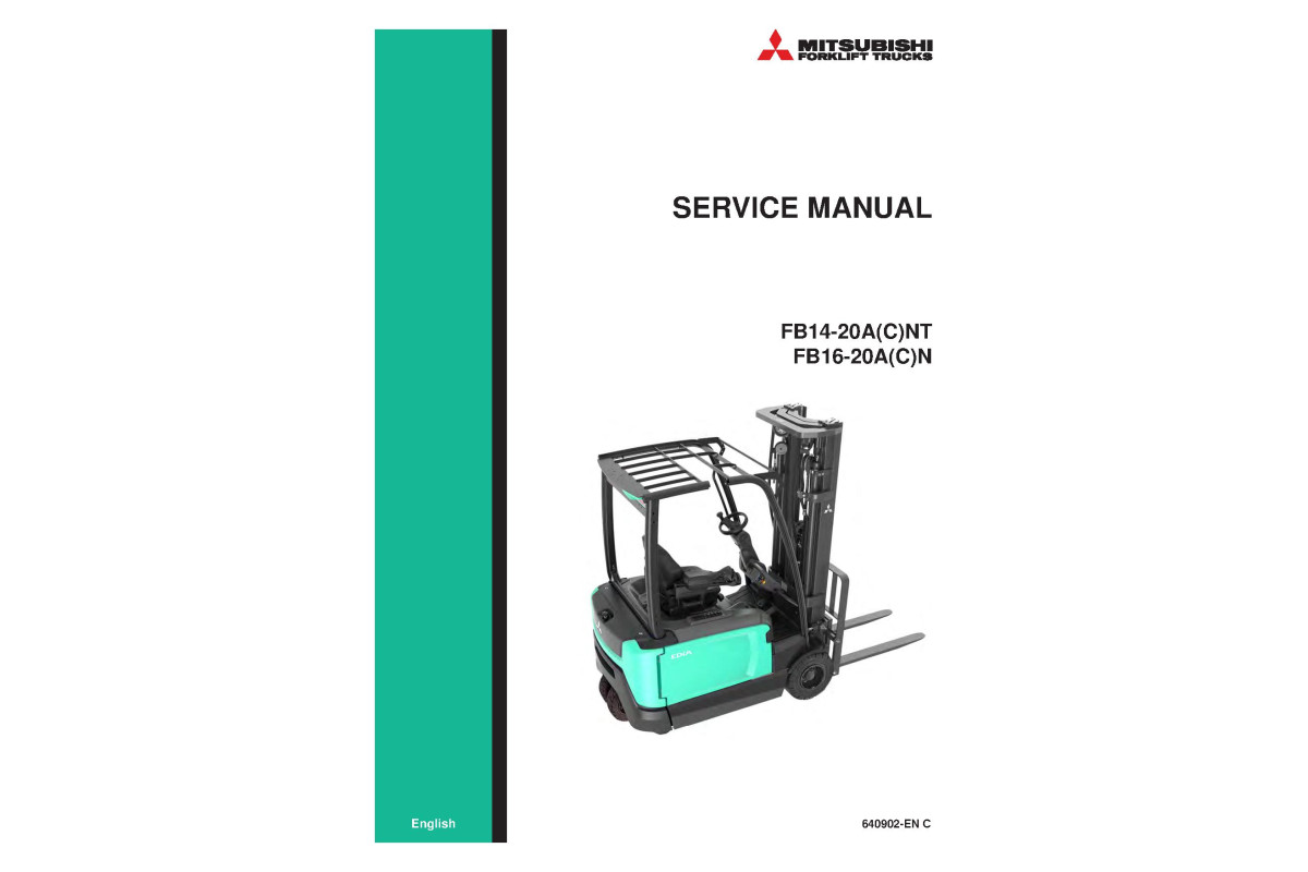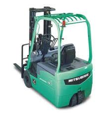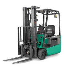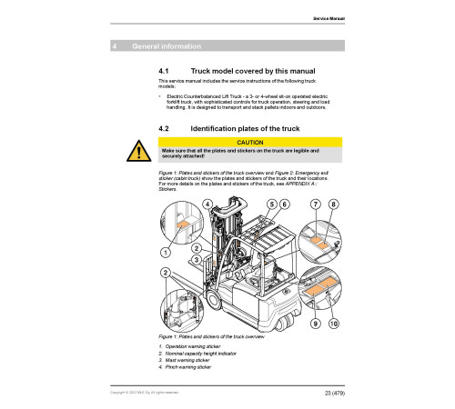
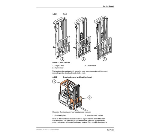


Illustrated factory set of Service Manuals for Mitsubishi Electric Forklift Trucks Models FB14ANT, FB14ACNT, FB16ANT, FB16ACNT, FB18ANT, FB18ACNT, FB20ANT, FB16AN, FB16ACN, FB18AN, FB18ACN and FB20AN.
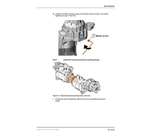
This manuals will assist you in diagnosing, analyses, testing, repair, operating, maintaining, and troubleshooting for your electric forklift truck.
You can use a Windows, Mac, or Android device to view this manuals. You only need to have a PDF reader installed.
Covered Models:
FB14ANT
FB14ACNT
FB16ANT
FB16ACNT
FB18ANT
FB18ACNT
FB20ANT
FB16AN
FB16ACN
FB18AN
FB18ACN
FB20AN
The manual comprises 8 documents, including the Service Manual, Operate and Maintenance manual, and 6 Wiring Diagrams
1. Service Manual (SM-640902-EN)
Format: PDF, 482 pages
Language: English
Table of Contents:
Foreword
How to read this manual
Safety-related signs
Symbols and abbreviations
Interactive links
Safety instructions
General safety instructions
Safety requirements for industrial trucks
Repairs and structural modifications
Service area safety
Personal safety
Work safety
Operating temperature
General information
Truck model covered by this manual
Identification plates of the truck
Overview of the truck
Mechanical Maintenance
Lifting points
Transportation
Assembly and commissioning
Order spare parts
How to clean the truck
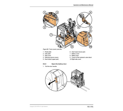
Truck covers overview
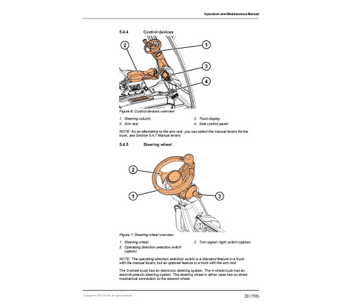
Steering wheel
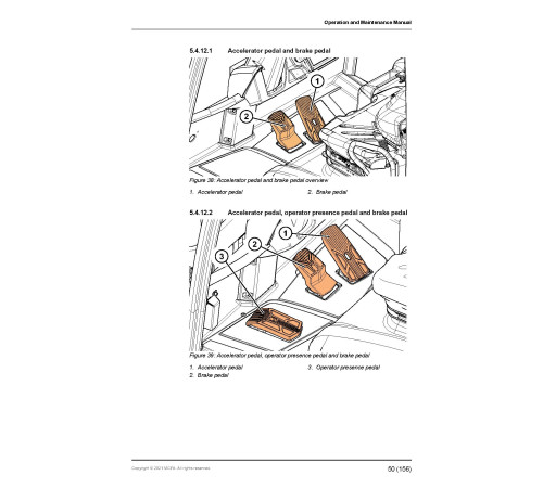
Pedals
Drive axle
Rear axle (3-wheel models)
Rear axle (4–wheel models)
Drive axle and rear axle maintenance
Wheels
Front wheels
Rear wheels
Mast
Hook-on sideshift
Integrated sideshift carriage
Integrated fork positioner with sideshift
Operator’s seat
Manual holder (cabin truck)
Arm rest
Cabin
Electrical operation
Overview
How to use the schematic diagram
Power source
Safety circuit (emergency stop button)
Key switch
Traction
Battery maintenance
General information
Safety with lead-acid batteries
Battery maintenance
Requirements for battery charging areas
Charge the battery
Measure the specific gravity of the battery
Replace the battery
Electric system maintenance
Display panel
Electric system
Motor compartment
Pump motor
Rear compartment
Sensors
Actuators
Electric system adjustments and measurements
Calibrate the arm rest levers
Insulation resistance test
Hydraulic operation
Hydraulic operation overview
Hydraulic operation lifting/lowering
Hydraulic symbols
Hydraulic oil recommendations
Hydraulic valve unit with fingertip controls
Hydraulic valve unit with manual levers
Hydraulic supply system
Hydraulic flow distribution with additional hydraulic functions
Hydraulic system maintenance
TruckTool Diagnostics
Overview
Location of the service socket
Parameter descriptions
Service data
Special tightening torques
Tightening torques for standard bolts and nuts
Maintenance check list
Oils and lubricants
Special tools
Troubleshooting
Options
Options
Accessory rack
A4 paper holder
Smart backup alarm
Rear Combination Light with Turn Signals
Amber strobe
Blue point front light
Blue point rear light
DC-DC converter
USB connector
Automated performance reduction based on lift height
Tilt angle sensor / display status indication with FC
Load weight indicator
Operator’s seat options and accessories
Fire extinguisher
Battery sideway exchange tools
Wide view mirror
Rear view mirror
External rear view mirrors
Hydraulic accumulator
Technical specifications
Dimensions
Technical data
APPENDIX A: Stickers
APPENDIX B: Truck display languages
APPENDIX C: Maintenance check list
APPENDIX D: Brake release
Index
2. Operate and Maintenance manual (OMM-654390-EN_0121)
Format: PDF, 160 pages
Language: English
Table of Contents:
Foreword
How to read this manual
Safety-related signs
Symbols and abbreviations
Interactive links
Safety instructions
Safety requirements for industrial trucks
Electromagnetic compatibility
Non-ionizing radiation
Noise
Vibration
Instructions for site supervision
Occupational safety
Requirements for the truck operator
Emergency procedures
Stability
Operation in areas containing hazardous flammable gases, liquid or other combustibles
Repairs and structural modifications
LOCKOUT and TAGOUT
Operating environment
Surface requirements
Bearing capacity of the floor
Operating temperature
Wind forces
Lighting
Driveways
Free space
Ramps
Dock levellers
Elevators
General information
Intended use
Prohibited use
Identification plates of the truck
Overview of the truck
Before operation
Daily maintenance before operation
Operator compartment adjustments
Operating instructions
How to operate the truck
How to activate the truck
Brakes
How to move the truck
General operating instructions
How to handle loads
Batteries
General information
Safety with lead-acid batteries
Battery maintenance
Requirements for battery charging areas
Charge the battery
Measure the specific gravity of the battery
Acquire a new battery
Replace the battery
Maintenance
Safety instructions for maintenance
Truck covers
Fuses
Troubleshooting
How to clean the truck
Daily maintenance
Weekly maintenance
Monthly maintenance
Annual (or 1,000 h) maintenance
Oils and lubricants
Dangerous waste and disposal
Order spare parts
Transportation and storage
Lifting points
Towing connection
Transportation
Storage
Decommissioning
Options
Options
Tilt angle sensor / display status indication with FC
Load weight indicator
Battery sideway exchange tools
Sun guard
Windshield washer (cabin truck)
Technical specifications
Dimensions
A Labels
B Truck display languages
C Maintenance check list
D Brake release
Index
3. Wiring Diagram (HY-DOC00036403-Rev.O)
Format: PDF, 2 pages
Language: English
Table of Contents:
3-7840_HS: FB14-20A(C)N(T) / HYDRAULIC DIAGRAM
1: MAIN CIRCUIT - FC
2: MAIN CIRCUIT - MC
4. Wiring Diagram (EL-E000409-EU)
Format: PDF, 22 pages
Language: English
Table of Contents:
E000409: EVOLT48 ANSI
0: CONTENTS
1: VOLTAGE SUPPLIES
2: MOTOR CONNECTIONS
3: ELECTRIC STEERING
4: CONTROLLERS KEY INPUTS
5: THROTTLE- AND BRAKE PEDAL
6: ARMREST
7: FC-VALVES
8: MC-VALVES
9: FANS AND SENSORS 1
10: SENSORS 2
11: ANTURIT 3
12: CAN-BUS
13: HORN AND STROBO-LIGHT
14: LIGHTS AND ACCESSORIES
15: LIGHTS AND AUX DEVICES 2
16: DATA COLLECTION SYSTEM
17: REAR COMB. LIGHT SWITCHES
18: REAR COMB.LIGHT+TURN SIGNALS
19: OPTION DCDC CONVERTERS AND FUSES
20: DELUXE CABIN+HEATER
21: DELUXE CABIN
5. Wiring Diagram (EL-E000389-EU)
Format: PDF, 22 pages
Language: English
Table of Contents:
E000389: EVOLT48 ANSI UL-E/-EE
0: CONTENTS
1: VOLTAGE SUPPLIES
2: MOTOR CONNECTIONS
3: ELECTRIC STEERING
4: CONTROLLERS KEY INPUTS
5: THROTTLE- AND BRAKE PEDAL
6: ARMREST
7: FC-VALVES
8: MC-VALVES
9: FANS AND SENSORS 1
10: SENSORS 2
11: ANTURIT 3
12: CAN-BUS
14: HORN SWITCHES
15: LIGHTS AND ACCESSORIES
16: LIGHTS AND AUX DEVICES 2
17: REAR COMB.LIGHT SWITCHES
18: REAR COMB.LIGHT+TURN SIGNALS
19: DCDC CONVERTERS AND FUSES
20: DELUXE CABIN
21: DELUXE CABIN
22: REVISION HISTORY
6. Wiring Diagram (EL-DOC00037100-Rev.K)
Format: PDF, 22 pages
Language: English
Table of Contents:
3-7840: EVOLT 48
0: CONTENTS
1: VOLTAGE SUPPLIES
2: MOTOR CONNECTIONS
3: ELECTRIC STEERING
4: CONTROLLERS KEY INPUTS
5: THROTTLE- AND BRAKE PEDAL
6: ARMREST
7: FC-VALVES
8: MC-VALVES
9: FANS AND SENSORS 1
10: SENSORS 2
11: CAN-BUS
12: HORN AND STROBO-LIGHT
13: LIGHTS AND ACCESSORIES
14: LIGHTS AND AUX DEVICES 2
15: DATA COLLECTION SYSTEM
16: ROAD LIGHT KIT SWITCHES
17: ROAD LIGHTS
18: OPTION DCDC CONVERTERS AND FUSES
19: DELUXE CABIN+HEATER
20: DELUXE CABIN
21: CABIN HEATER
7. Wiring Diagram (EL-DOC00037100-EU)
Format: PDF, 22 pages
Language: English
8. Wiring Diagram (EL-DOC00033554-Rev.P)
Format: PDF, 39 pages
Language: English
Included
Service Manual
1Operate and Maintenance manual
1Wiring Diagram
6Reviews: 0
There are no reviews for this product.
Questions: 0
No questions about this product.
Похожие товары

