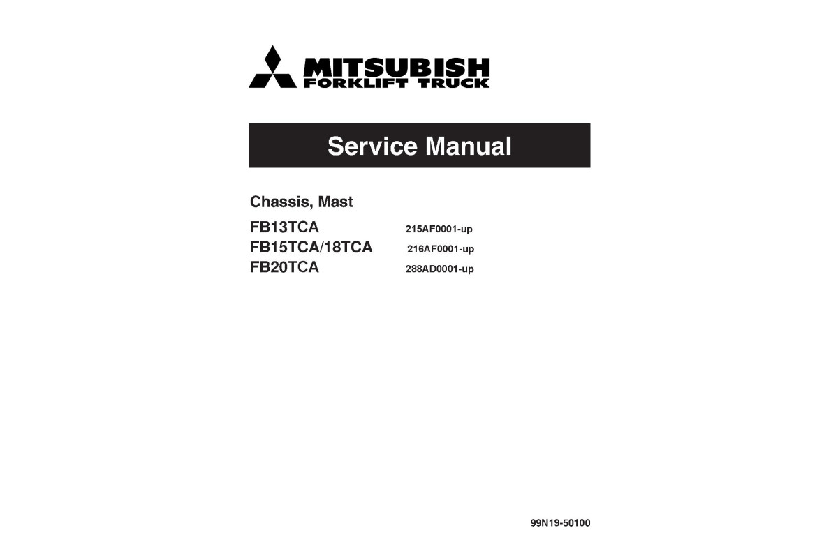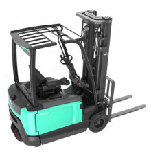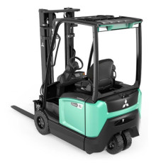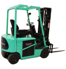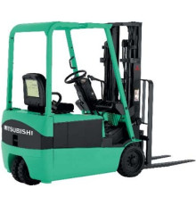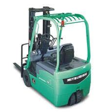
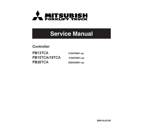


Illustrated factory set of Service Manuals for Mitsubishi Electric Forklift Trucks Models FB13TCA (215AF0001-up), FB15TCA (216AF0001-up), FB18TCA (216AF0001-up) and FB20TCA (288AD0001-up).
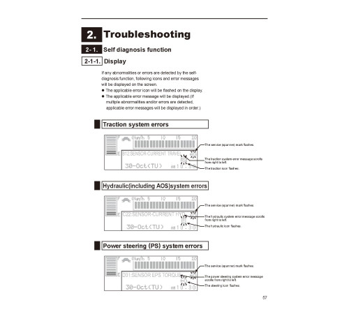
This manuals will assist you in diagnosing, analyses, testing, and repair for your electric forklift truck.
You can use a Windows, Mac, or Android device to view this manuals. You only need to have a PDF reader installed.
Covered Models:
FB13TCA (215AF0001-up)
FB15TCA (216AF0001-up)
FB18TCA (216AF0001-up)
FB20TCA (288AD0001-up)
The manual comprises two Service Manuals
1. Service Manual: Controller (SM-99N19-52100_Controller_E08)
Format: PDF, 108 pages
Language: English
Table of Contents:
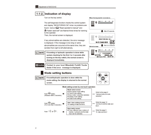
Adjustment of SICOS-AC
Troubleshooting
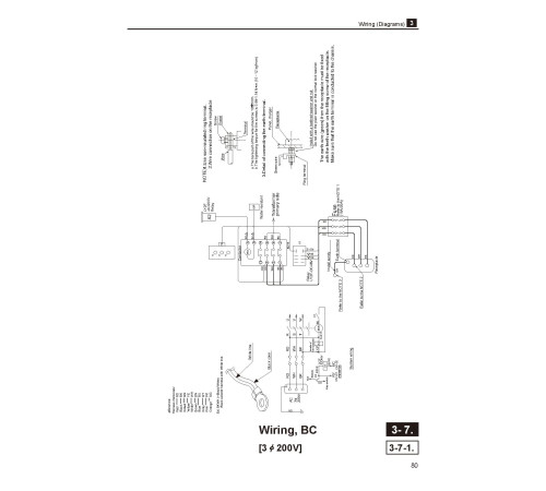
Wiring (Diagrams)
Reference
2. Service Manual: Chassis, Mast (SM-99N19-50100_E08)
Format: PDF, 189 pages
Language: English
Table of Contents:
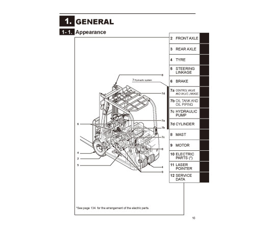
1. GENERAL
1-1. Appearance
1-2. Specifications
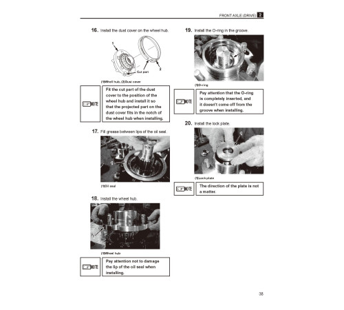
2. FRONT AXLE (DRIVE)
2-1. Disassembly and reassembly
2-1-1. Front axle - removal
2-1-2. Disassembly transfer ASS`Y
2-1-3. Reassembly the transfer ASS`Y
3. REAR AXLE (STEERING)
3-1. Disassembly and reassembly
3-1-1. Rear axle - removal and installation
3-1-2. Rear axle - disassembly and reassembly
3-2. Inspection and adjustment
3-2-1. Angle sensor comp. - adjustment
3-2-2. EPS torque sensor - adjustment
3-3. Troubleshooting
3-3-1. Rear axle - troubleshooting
4. TYRE
4-1. Front tyre
4-1-1. Front tyre - disassembly and reassembly
4-1-2. Tyre size (front)
4-2. Rear tyre
4-2-1. Rear tyre - disassembly and reassembly
4-2-2. Tyre size (rear)
4-3. Inspection and adjustment
4-3-1. Bolt nut - inspection
4-3-2. Air pressure - inspection
4-3-3. Tyre - visual inspection and replacement
4-4. Troubleshooting
4-4-1. Tyre - troubleshooting
5. STEERING LINKAGE
5-1. Disassembly and reassembly
5-1-1. Steering linkage- disassembly and reassembly
5-2. Inspection and adjustment
5-2-1. Joint - inspection and replacement
5-2-2. Knob - inspection and replacement
5-2-3. Steering wheel - inspection and replacement
5-2-4. Chain comp., roller - adjustment
6. BRAKE
6-1. Foot brake
6-1-1. Foot brake - disassembly and reassembly
6-2. Parking brake
6-2-1. Parking brake - disassembly and reassembly
6-3. Inspection and adjustment
6-3-1. Brake pedal - adjustment
6-3-2. Brake pedal - inspection
6-3-3. Microswitch of parking brake lever - adjustment
6-3-4. Parking lever - inspection and adjustment
6-3-5. Master cylinder ASS`Y- inspection and replacement
6-3-6. Master cylinder air bleeding
6-4. Troubleshooting
6-4-1. Brake - troubleshooting
7. HYDRAULIC SYSTEM
7-1. Oil piping circuit
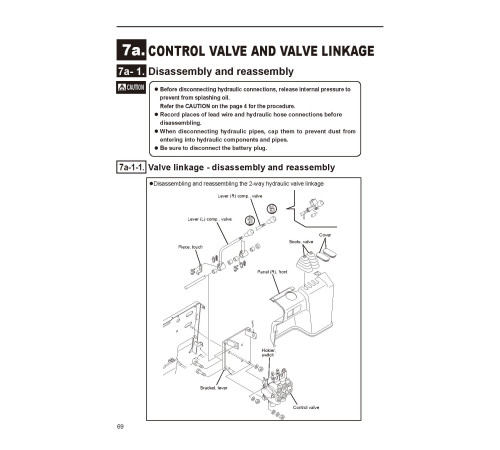
7a CONROL VALVE AND VALVE LINKAGE
7a-1. Disassembly and reassembly
7a-1-1. Valve linkage - disassembly and reassembly
7a-1-2. Control valve
7a-2. Inspection and adjustment
7a-2-1. Relief pressure - adjustment
7a-2-2. Microswitch - adjustment
7a-3. Trouble shooting
7a-3-1. Control valve - troubleshooting
7b. OIL TANK AND OIL PIPING
7b-1. Disassembly and reassembly
7b-1-1. Oil tank - disassembly and reassembly
7b-1-2. Oil piping replacement - precautions
7b-2. Inspection and adjustment
7b-2-1. Oil - inspection
7b-2-2. Recommended oil and quantity for hydraulic circuit (except brake and gear oil)
7b-2-3. Oil tank and filters - cleaning and check
7b-3. Troubleshooting
7b-3-1. Oil tank - troubleshooting
7c. HYDRAULICPUMP
7c-1. Removal and installation
7c-1-1. Hydraulic pump -removal and installation
7d. CYLINDER
7d-1. Disassembly and reassembly
7d-1-1. Lift cylinder - removal : 2SP - mast (2 - stage simplex)
7d-1-2. Lift cylinder - removal : 2FP-mast (2-stage duplex), 3FP-mast (3-stage triplex
7d-1-3. Tilt cylinder - removal
7d-1-4. Lift cylinder - installation and adjustment
7d-1-5. Tilt cylinder - installation
7d-1-6. Lift cylinder - disassembly and reassembly
7d-1-7. Tilt cylinder - disassembly and reassembly
7d-2. Inspection and adjustment
7d-2-1. Cylinder comp. - inspection
7d-2-2. Piston rod - inspection
7d-2-3. Drift for lift and tilt - inspection
7d-3. Variation of the tilt cylinder
7d-3-1. Tilt angle by masts
7d-4. Troubleshooting
7d-4-1. Cylinder - troubleshooting
8. MAST
8-1. Disassembly and reassembly
8-1-1. Lift bracket ASS`Y- removal
8-1-2. Mast ASS`Y - removal
8-1-3. Mast - disassembly and reassembly
8-2. Inspection and adjustment
8-2-1. Mast, lift bracket and roller shaft - inspection
8-2-2. Back shoe - inspection
8-2-3. Lift chain - inspection and replacement
8-2-4. Chain bolt - inspection
8-2-5. Chain wheel - inspection
8-2-6. Roller - inspection and replacement
8-2-7. Fork - inspection and replacement
8-2-8. Lift chain - inspection and adjustment
8-2-9. Mast lean- adjustment
8-3. Troubleshooting
8-3-1. Mast Lift bracket Fork - troubleshooting
9. MOTOR
9-1. Disassembly and reassembly
9-1-1. Traction motor - removal and installation
9-1-2. Hydraulic motor - removal and installation
9-1-3. EPS motor - removal and installation
9-1-4. Traction motor - disassembly and reassembly
9-1-5. Hydraulic motor - disassembly and reassembly
9-1-6. EPS motor - disassembly and reassembly
9-2. Inspection and adjustment
9-2-1. Rotor comp. (Traction/hydraulic motor) - inspection and replacement
9-2-2. Armature comp. (EPS motor) - inspection and replacement
9-2-3. Brush, brush holder and spring (EPS motor) - inspection and replacement
9-2-4. Motor ASS`Y (Traction/Hydraulic motor) - inspection
9-2-5. Motor ASS`Y (EPS motor) - inspection
9-2-6. Oil seal and permanent magnet (EPS motor) inspection and replacement
9-2-7. Motor - specification
9-3. Troubleshooting
9-3-1. Motor - troubleshooting
10. ELECTRIC PARTS
10-1. Location and name
10a. CONTROL UNIT
10a-1. Location and name
10a-2. Disassembly and reassembly
10a-2-1. Control unit - removal and installation
10a-2-2. EPS controller - removal and installation
10a-2-3. Control unit - disassembly and reassembly
10a-3. Check and replacement
10a-3-1. Main connector - inspection and replacement
10a-3-2. Module, FET - inspection and replacement
10a-3-3. Capacitor - check and replacement
10b. ACCELERATOR
10b-1. Disassembly and reassembly
10b-1-1. Accelerator linkage - removal and installation
10b-2. Inspection and adjustment
10b-2-1. Potentiometer - adjustment
10b-2-2. Accelerator linkage - adjustment
10c. DISPLAY PANEL AND DIRECTIONAL SWITCH
10c-1. Disassembly and reassembly
10c-1-1. Display panel - disassembly and reassembly
10c-1-2. Directional switch - disassembly and reassembly
10d. BATTERY
10d-1. Removal and installation
10d-1-1. Battery - removal and installation
10d-2. Inspection and adjustment
10d-2-1. Battery - inspection and adjustment
10d-2-2. Battery - Cleaning
10e. CHARGER (BUILT - IN)
10e-1. Disassembly and reassembly
10e-1-1. Charger ASS`Y - disassembly and reassembly
10e-1-2. Transformer - disassembly and reassembly
10e-1-3. Built-in charger - specification
10e-2. Inspection and replacement
10e-2-1. Magnetic contactor - inspection
10e-2-2. Plug comp. and receptacle - inspection and replacement
10e-2-3. Fuse and fuse base - inspection
10e-2-4. Transformer - inspection
10e-2-5. Diode - inspection
10e-3. Inspection After Assembly
10e-3-1. Timer - inspection
10e-4. Charging procedure
10e-4-1. Automatic charge (Daily charge)
10e-4-2. Balancing charge
10e-4-3. Inspection after charging
10e-5. Voltage tap
10e-5-1. Power supply voltage - check
10e-5-2. Voltage tap - selection
10e-5-3. Voltage tap - changing
10e-5-4. Fuse (three-phase voltage) - replacement
11. LASER POINTER (OPTION)
11-1. Adjustment
11-1-1. Fork level - adjustment
11-1-2. Laser optical axis - adjustment
12. SERVICE DATA
12-1. Standard work hours
Included
Service Manual
2Reviews: 0
There are no reviews for this product.
Questions: 0
No questions about this product.
Похожие товары

