

$49.99
Fault Codes List
1Service Manual
2Operate and Maintenance manual
1Wiring Diagram
2Special Instruction
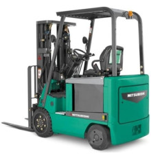
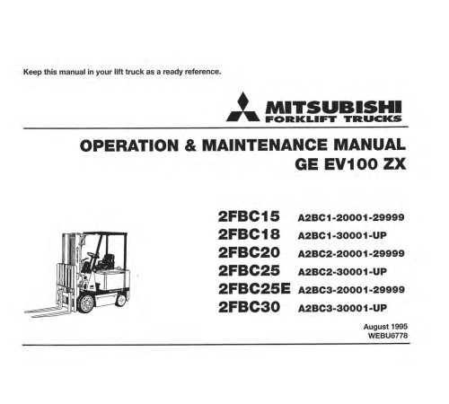
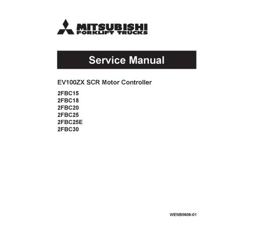
1Illustrated factory set of Service Manuals for Mitsubishi Electric Forklift Trucks Models 2FBC15 (A2BC1-20001-29999), 2FBC18 (A2BC1-30001-UP), 2FBC20 (A2BC2-20001-29999), 2FBC25 (A2BC2-30001-UP), 2FBC25E (A2BC3-20001-29999) and 2FBC30 (A2BC3-30001-UP).
This manuals will assist you in determining a malfunction using a fault code, diagnosing, analyses, testing, repair, operating, maintaining, troubleshooting, and repairing for your electric forklift truck.
You can use a Windows, Mac, or Android device to view this manuals. You only need to have a PDF reader installed.
Covered Models:
2FBC15 (A2BC1-20001-29999)
2FBC18 (A2BC1-30001-UP)
2FBC20 (A2BC2-20001-29999)
2FBC25 (A2BC2-30001-UP)
2FBC25E (A2BC3-20001-29999)
2FBC30 (A2BC3-30001-UP)
The manual comprises 7 documents, including the Fault Codes List, two Service Manuals, Operate and Maintenance manual, two Wiring Diagrams, and Special Instruction
1. Fault Codes List (REF-18-0008M_69904)
Format: PDF, 13 pages
Language: English
2. Service Manual: EV100ZX SCR Motor Controller (SM-WENB8606-01)
Format: PDF, 148 pages
Language: English
Table of Contents:
GENERAL INFORMATION & FEATURES
Glossary
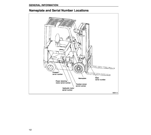
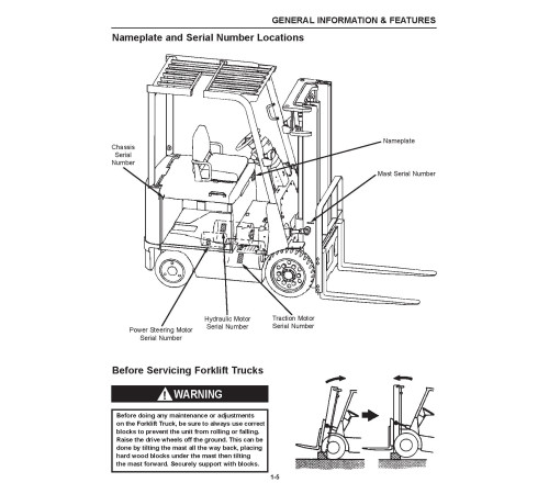
Nameplate and Serial Number Locations
EV100ZX Motor Controller without SCR Hydraulics
EV100ZX Motor Controller with optional SCR Hydraulics
Basics of Circuit Operation
Traction Control Logic Flow Chart
Console (Display)
Features of the EV100ZX Control System
General Maintenance for the EV100ZX Motor Controller
Trouble-shooting the EV100ZX Motor Controller
EV100ZX SCR Control Wiring Schematic without SCR Hydraulics
EV100ZX SCR Control Wiring Schematic with SCR Hydraulics
EV100ZX SCR Control Wiring Schematic for Optional Equipment
HANDSET
General Information
Handset Function
Operation
Function Set-Up Procedures for Traction SCR
Accessing and Clearing Fault Codes
Bench Checks and Adjustments
Function Numbers (Traction)
Function Settings Chart (Traction Card)
Function Set-Up Procedures for Optional SCR Hydraulics
Function Numbers (Pump)
Function Settings (Pump Card)
CHECKS & REPAIRS
General Information
Fuses
SCR’s
Thermal Protector
Reactor Assembly
Suppressors
Capacitor C1
Diodes D3, D4 & D7
Motor Current Sensor
Thermal Protector Test
Contactors
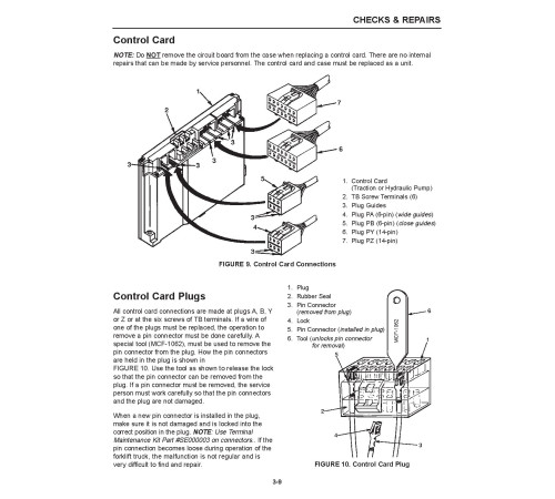
Control Card
Control Card Plugs
Brush Wear Indicators
Motor Thermal Switches
Motors and Controls
Truck Management Module (TMM)
Truck Management Module Connections (TMM1)
Thermal Transfer
Trouble Shooting Tips
Unsatisfactory Brush Performance
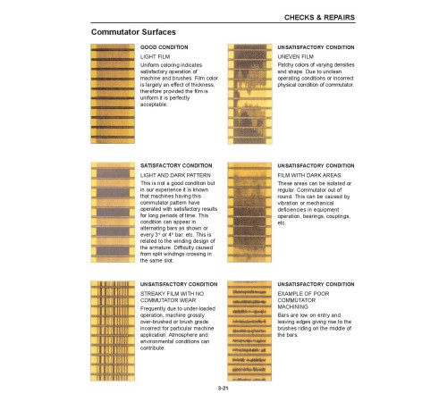
Commutator Surfaces
Motor Winding Specifications
LOGIC CARD CONNECTIONS & TROUBLESHOOTING BY SYMPTOM
Main Logic Card
Component Locations
Terminal Connections for ZX Logic Cards
EV100ZX Logic Card Specifications
EV100ZX Current Limit Curves
Secondary Troubleshooting
Failures that Cause Reduced or No Motor Torque with SCR Control
Failures that Cause Full or No Motor Torque with SCR Control
Mis-operation of Other Features
Hydraulic Pump Control Troubleshooting
Failures that Cause Reduced or No Motor Torque with SCR Control
Failures that Cause No Motor Torque with SCR Control
THEORY OF OPERATION
Electronic Speed Controls
Silicon Controlled Rectifier (SCR)
Motor Circuit that Operates with Pulses
Traction Circuit
Hydraulic Pump Motor
SCR “OFF” Circuit
Flyback Current from the Motor
Control Cards
Pulse Monitor Trip (PMT) (Traction Circuit Only)
SRO Circuit (Traction Circuit Only)
Sequence of Operation
Control Card Adjustments (Traction Circuit Only)
Accelerator Control
SCR Control (Hydraulic Pump Motor)
Contactors
Circuit Protection
Traction Circuit Fuse
Current Limit
Thermal Protection
Truck Management Module (TMM1)
Instrument Panel
Fault Code Memory
Brush Wear Indicators
WIRING
Power Cable Connections
Standard Control
Optional SCR Hydraulics Control
Traction Control Card Wire Harness Connections
A & B Plugs
Y Plug
Z Plug
TMM1 (Truck Management Module 1)
TB Connections
Control Card Wire Harness for Optional Hydraulic Pump SCR
Panel Connector
TB Connections
A & B Plugs
Y Plug
Z Plug for Use on Option Card
Pump Driver
Pump Time Delay
DIAGNOSTIC STATUS CODES
Basic Checks
On Board Diagnostics
Status Codes
3. Service Manual (SM-99759-70100_0199)
Format: PDF, 290 pages
Language: English
Table of Contents:
General Information
Scope
Truck Models Covered
Nameplate and Serial Number Locations
Dimensions
Dimensions Chart
General Information (Standard Models)
Front Axle & Reduction Differential
Description
Front Axle
General Information
Front Wheels
Removal
Installation
Axle Disassembly
Removing Front Wheel Hub
Inspection after Disassembly
Axle Shafts
Reassembly
Axle Housing
Front Wheel Hub
Hub Bearing Preload
Reduction Differential
Description
Disassembly
Removing Bearing Inner Races
Inspection after Disassembly
Reduction Gear
Differential
Reassembly
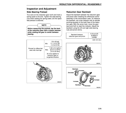
Inspection and Adjustment
Side Bearing Preload
Reduction Gear Backlash
Reduction Gear Face Runout
Tooth Contact
Tooth Contact Adjustment
Transfer Case
Description
Earlier Version
Later Version
Disassembly
Removal
Reassembly
Rear Axle
Description
Rear Axle
Rear Wheels
Removal
Installation
Rear Axle
Removal
Installation
Disassembly
Inspection after Disassembly
Reassembly
Inspection and Adjustment
Minimum Turning Radius Adjustment
Brake System
Description
Automatic Adjusting Device
Master Cylinder
Disassembly/Earlier Version
Disassembly/Later Version
Inspection after Disassembly
Reassembly
Service Brakes
Disassembly (2FBC15/18)
Disassembly (2FBC20/25/25E/30)
Inspection after Disassembly
Reassembly (2FBC15/18)
Reassembly (2FBC20/25/25E/30)
Wheel Cylinders
Disassembly/Earlier Version
Disassembly/Later Version
Inspection after Disassembly
Reassembly
Inspection and Adjustment
Steering System
Description
Steering System with EV100ZX Controller
Oil Flow Sequence
General Information
Steering System with Optional TR3000 Controller
Oil Flow Sequence
General Information
Steering Gear
Removal
Steering Gear with EV100ZX Controller
Steering Gear with Optional TR3000 Controller
Inspection after Removal
Installation
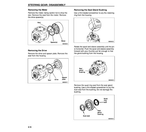
Disassembly
Steering Gear with EV100ZX Controller
Steering Gear with Optional TR3000 Controller
Inspection after Disassembly
Reassembly
Truck with EV100ZX Controller
Truck with Optional TR3000 Controller
Inspection after Reassembly
Steer Pump - Trucks with EV100ZX Controller Only
Removal
Installation
Disassembly
Inspection after Disassembly
Reassembly
Inspection after Reassembly
Hydraulic System
Description
Schematic for Trucks with EV100ZX Controller
Schematic for Trucks with Optional TR3000 Controller
Hydraulic Tank
Hydraulic Pump for Trucks with EV100ZX Controller
Hydraulic Pump for Trucks with Optional TR3000 Controller
Control Valve
Lift and Tilt Cylinders
Flow Regulator Valve
Down Safety Valve
Removal and Installation General Warning
Hydraulic Pump
Removal
Trucks with EV100ZX Controller
Trucks with Optional TR3000 Controller
Installation
Trucks with EV100ZX Controller
Trucks with Optional TR3000 Controller
Disassembly
Trucks with EV100ZX Controller
Trucks with Optional TR3000 Controller
Inspection after Disassembly
Body
Bushes and Balance Plate
Gears
Priority Valve (Trucks with Optional TR3000 Controller Only)
Disassembly
Reassembly
Control Valve
Removal
Trucks with EV100ZX Controller
Trucks with Optional TR3000 Controller
Installation
Disassembly
Inspection after Reassembly
Reassembly
Lift and Tilt Cylinders
Removal
Lift Cylinders/Earlier Version
Lift Cylinders/Later Version
Installation
Tilt Cylinders/Earlier Version
Tilt Cylinders/Later Version
Disassembly
Lift Cylinders
Tilt Cylinders/Earlier Version
Tilt Cylinders/Later Version
Inspection after Disassembly
Precautions for Reassembly
Flow Regulator Valve
Disassembly
Inspection and Adjustment
Hydraulic Tank
Control Valve
Lift and Tilt Cylinders
Adjusting Method
Testing
Mast and Forks/Earlier Version
Description
Components
Removal and Installation
Mast and Lift Bracket Assembly
Disassembly
Inspection after Disassembly
Reassembly
Inspection and Adjustment
Forks
Chain Tension Adjustment
Clearance Adjustment on Lift Bracket
Mast Clearance Adjustment
Main Roller Shim Replacement
Mast Adjustment Chart
Mast and Forks/Later Version
Description
Components
Removal and Installation
Mast and Lift Bracket Assembly
Disassembly
Inspection after Disassembly
Reassembly
Inspection and Adjustment
Forks
Chain Tension Adjustment
Clearance Adjustment on Lift Bracket
Mast Clearance Adjustment
Main Roller Shim Replacement
Mast Strip Adjustment
Tilt Angle Adjustment
Lift Cylinder Stroke Adjustment
Bleeding Lift Cylinders
Service Data
Troubleshooting
Troubleshooting Section
Front Axle and Reduction Differential
Brake System
Steering System
Hydraulic System
Rear Axle
Mast and Forks
Maintenance Service Data Section
Maintenance Service Data
Front Axle and Reduction Differential
Transfer Case
Rear Axle
Brake System
Steering System
Hydraulic System
Mast and Forks (Simplex Mast)
Tightening Torques for Standard Bolts and Nuts
Fine Thread - With Spring Washer
Fine Thread - Without Spring Washer
Coarse Thread - With Spring Washer
Coarse Thread - Without Spring Washer
Maintenance Chart
Periodic Replacement Parts
Lubrication
Lubrication Chart
Fuel and Lubricant Specifications
Recommended Brands of Lubricants
Weight of Major Components (Approximate)
Special Service Tools
Special Tool Illustrations
Inspection Guide
4. Operate and Maintenance manual (OMM-WEBU6778_0895)
Format: PDF, 116 pages
Language: English
5. Wiring Diagram: without SCR (WENB8614t_48210)
Format: PDF, 2 pages
Language: English
6. Wiring Diagram: with SCR (WENB8608t_48211)
Format: PDF, 2 pages
Language: English
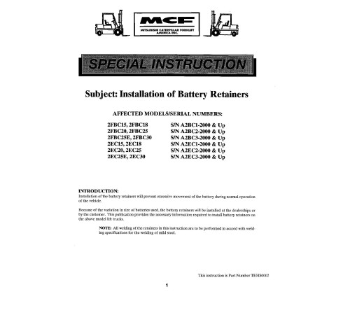
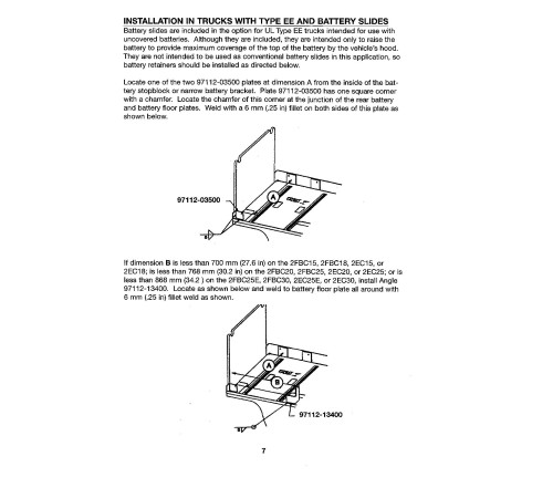
7. Special Instruction: Installation of Barttery Retainers (TEHS0002_50508)
Format: PDF, 12 pages
Language: English
Included
Fault Codes List
1Service Manual
2Operate and Maintenance manual
1Wiring Diagram
2Special Instruction
1Reviews: 0
There are no reviews for this product.
Questions: 0
No questions about this product.
Похожие товары

