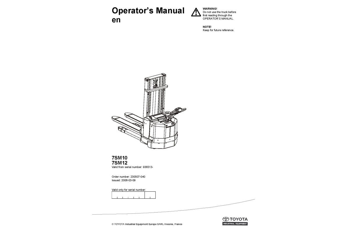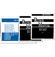
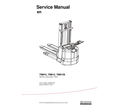


Illustrated factory set of Service Manuals for Toyota Pallet Stackers Models 7SM10 and 7SM12 (SN:936513-up).
This manuals will assist you in diagnosing, analyses, testing, repair, operating, and maintaining for your pallet stacker.
You can use a Windows, Mac, or Android device to view this manuals. You only need to have a PDF reader installed.
Covered Models:
7SM10 (SN:936513-up)
7SM12 (SN:936513-up)
The manual comprises 2 documents, including the Service Manual, and Operate and Maintenance manual
1. Service Manual (SM-226306-040)
Format: PDF, 182 pages
Language: English
Table of Contents:
General product information - M2
Intended application of the truck
Prohibited application of the truck
Truck data
Truck dimensions
Identification plate
Capacity plate
Modification plate
Main components
Warning and information plates and symbols
Technical data - M4
Introduction Maintenance - P1
Safety regulations with maintenance work
Cleaning and washing
Safe lifting
Preventive maintenance - P2
Maintenance schedule
Lubrication schedule
Oil and grease specification - P3
Tools - P4
Super Seal connectors
AMP connectors
Molex connectors
Grease guns
Other tools
Support arm chassis - 0350
General
Main components
Maintenance
Adjustment of the support arm width
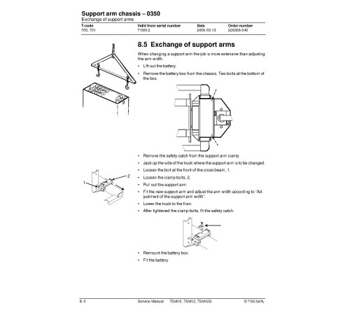
Exchange of support arms
Electric drive motor - 1760
Component parts
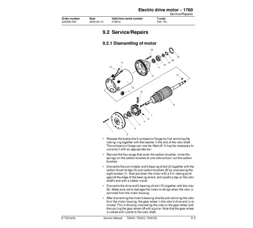
Service/Repairs
Technical data
Drive unit/gear - 2550
Component parts
Leakage from top cover
Changing of the drive shaft’s sealing ring
Electro magnetic brake - 3370
Main components
Maintenance
Steering - 4000
Component parts, tiller arm
Adjustments
Tiller arm handle
Electrical systems
General
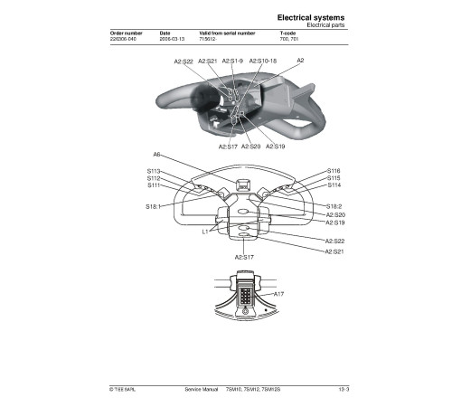
Electrical parts
Electrical wiring diagram
Functional description
Parameters
Diagnostic and troubleshooting
Technical specifications - Curtis 1243
Hydraulic system - 6000
General
Hydraulic diagram and components
Lifting Mast - 7000
Grease the beam flanges and beam ribs
Main lift chain system
Cleaning
Lubrication
Battery charger (built-in) - 8340
General
Technical data - charger
Charging
Troubleshooting and service
Setting the charger (applies to machine numbers 723984-936512)
Control/computer equipment - 8700
General
Connection
Layout
Connection function
Disconnection function
Downloading program function
Truck report function
Parameters function
Diagnostics function
Other menu functions
Specifications
Installation
2. Operate and Maintenance manual (UM-230507-040)
Format: PDF, 65 pages
Language: English
Table of Contents:
SM10 7SM12
Valid from serial number: 936513-
Order number: 230507-040
Safety regulations
Warning symbols
General safety regulations
Warning and information plates and symbols
Hydraulic control: Lifting/Lowering
Travel direction
Signal/Horn
Capacity plate
Identification plate
Hydraulic control: Lower
Serial number
Hydraulic oil filling
Maximum height for rated capacity
A) Do not walk under an elevated load B) Do not stand on the forks
Lifting points
Modification plate.
Presentation of the truck
Intended application of the truck
Prohibited application of the truck
Truck data
Truck dimensions
Identification plate
Capacity plate
Modification plate
Main components
Tiller arm: The truck is manoeuvred by the driver while walking. 208 degree steering area. The brakes are applied in the tiller arm’s upper and lower positions.
Identification plate: With model designation, serial number, year of manufacture, weight without battery, battery weight, rated capacity, battery voltage and manufacturer.
Covers: Removable which provides good accessibility when servicing.
Emergency switch off
Hydraulic control: For controlling lifting and lowering functions.
Hydraulic unit: Pump motor, pump and oil tank are integrated in a compact unit.
Hydraulic valves: The valves are located to provide easy access.
Drive unit with brake: Suspended drive unit with spring-loaded mechanical brake, travel motor, gears and drive wheel combined into a compact unit. Steering bearings between motor and gears.
Serial number: The serial number plate fitted to the chassis.
Electric panel: Removable, which provides good access when servicing. 24 volt electrical supply. The speed is variably controlled by means of a transistor.
Support castor wheels Two support castor wheels to ensure stability.
Battery: 24V with different Ah values. The battery is automatically locked in the battery compartment.
Battery connector: The battery is charged via the battery connector, which is usually connected to the battery disconnector.
Mast: Fitted with a finger guard to cover the driver's normal reach.
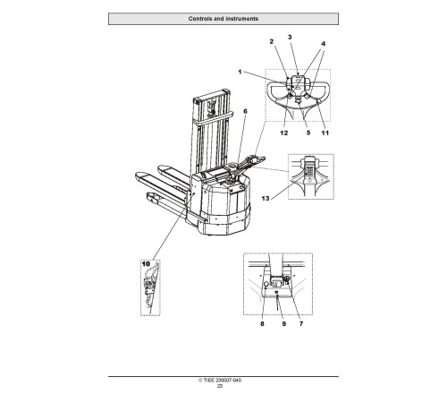
Controls and instruments
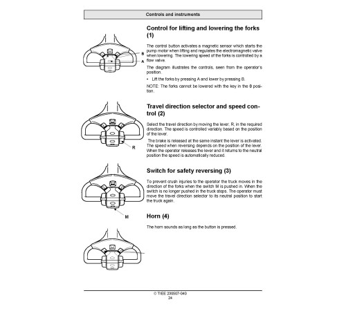
Control for lifting and lowering the forks
Travel direction selector and speed control
Switch for safety reversing
Horn
Display
Tiller arm and brake
Control for lowering the forks
Emergency switch off
Key switch
Battery connector
Turtle button (Option)
Click-2-Creep function (Option)
Keypad (Option)
Control for lifting and lowering the forks (1)
Travel direction selector and speed control (2)
Switch for safety reversing (3)
Horn (4)
Display (5)
Function
Tiller arm and brake (6)
Control for lowering the forks (7)
Emergency switch off (8)
Key switch (9)
Battery connector (10)
Display and programming
Display
Programming
Warning codes
Error codes
Accessories
Platform
Load support
Pen holder
Integrated charger
Turtle button
Click-2-Creep function
Keypad
ID unit
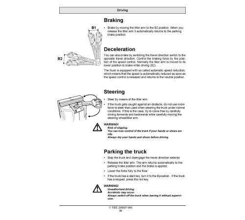
Driving
Starting the truck
Braking
Deceleration
Steering
Parking the truck
Transporting loads
WARNING!
WARNING!
WARNING!
WARNING!
WARNING
WARNING!
WARNING!
Collecting a load
Depositing a load
Battery
Replacing the battery
Charging the battery
Battery maintenance
Daily service and function checks
WARNING!
Pos no
Check points
Action
Maintenance
Safety regulations with maintenance work
Maintenance work that is to be carried out by the operator
Maintenance work that may be carried out by trained maintenance personnel
Cleaning and washing
Maintenance chart
Lubrication chart
Oil and grease specification
Transporting and storing the truck
The truck’s dimensions and weight as standard
Lifting the truck
Towing and transporting a defective truck
Storing the truck
Starting after a period of disuse
Recycling/discarding
Discarding the battery
Scrapping the truck
________________
Included
Service Manual
1Operate and Maintenance manual
1Reviews: 0
There are no reviews for this product.
Questions: 0
No questions about this product.
Похожие товары

